


Product Details
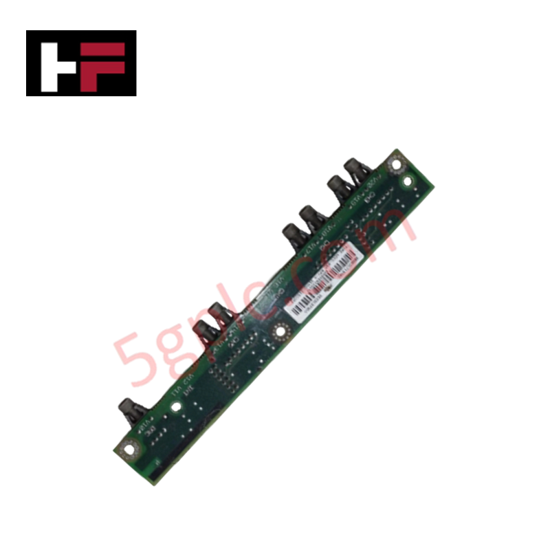
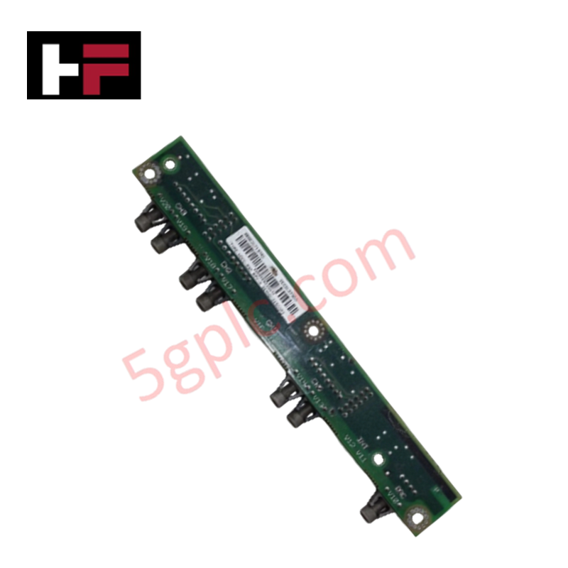
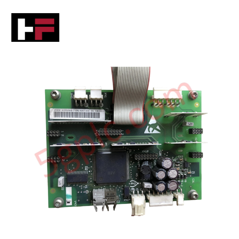
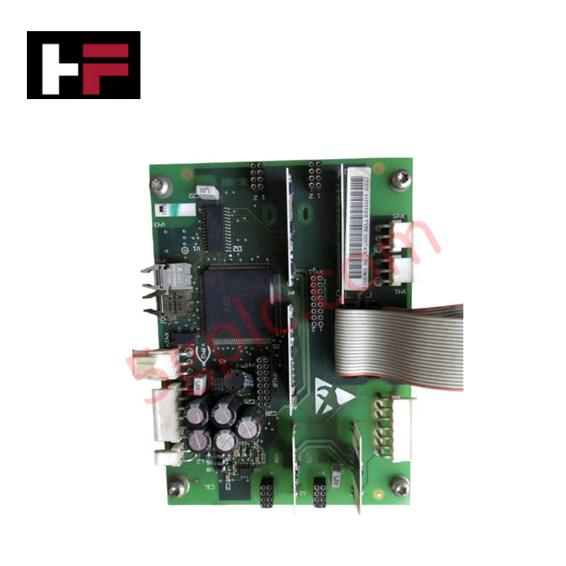
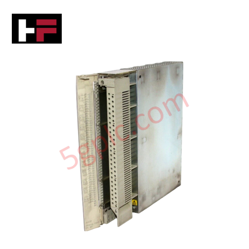
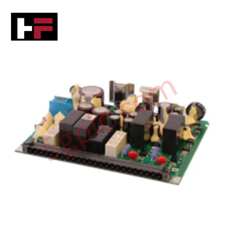
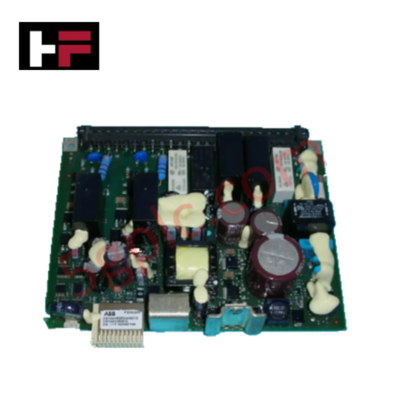
Configured for point-to-point and multi-node optical communication in high-interference topologies, the ABB 3BSE017197R1 (NDCO-03C Fiber Optic PCB Module) provides direct physical/electrical execution.
Hardware Specifications
| Parameter | Specification |
|---|---|
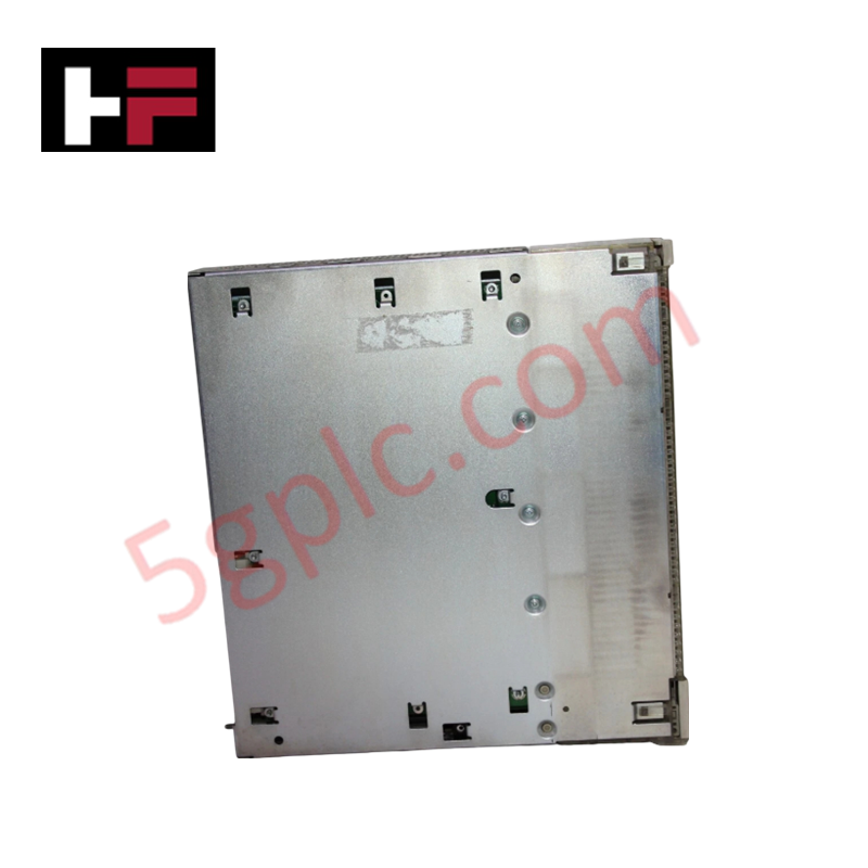
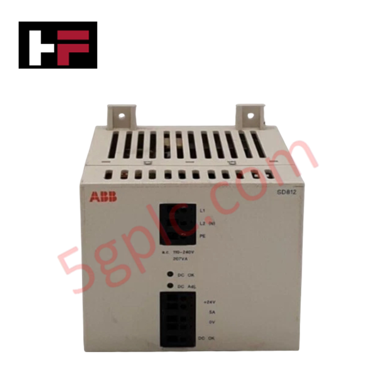
| Model | 3BSE017197R1 (NDCO-03C) |
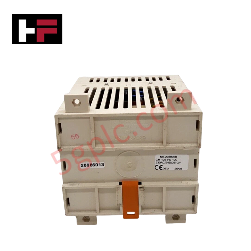
| Brand | ABB |
| Origin | Sweden or Switzerland |
| Weight | 0.3 kg |
| Dimensions | 150 x 50 x 20 mm |
| Operating Temp | Standard industrial drive cabinet specification |
| Power Consumption | Derived from internal host drive chassis interface |
| Communication System | ABB DDCS (Digital Data Communication System) |
| Transmission Medium | Fiber-optic cable |
| Optical Ports | Multi-channel optical interfaces (TX/RX pairs) |
| Electrical Isolation | Full optical isolation |
| Mounting Type | Internal option board, plug-in type |
Profinet / EtherNet/IP Deterministic Networks and I/O Density Scaling
The ABB 3BSE017197R1 manages real-time drive-to-drive transmission frames across the proprietary DDCS ring or star network. Its high-speed optical transceiver circuitry implements full galvanic separation, preventing localized high-voltage faults or common-mode noise from disrupting central control planes. In setups requiring synchronous I/O density scaling across multi-axis drive arrangements, this module functions as an isolated bridge, preserving frame priorities matching Profinet / EtherNet/IP deterministic networks properties. Continuous data processing profiles remain fully stable through varying link loads, ensuring strict firmware flash compatibility across legacy and contemporary drive processing architectures.
Frequently Asked Questions
Q: Does the NDCO-03C module support live hot-swapping while the host drive controller is active?
A: No. Plugging or unplugging the internal option board while the host controller backplane is energized will interrupt the DDCS optical ring, trigger immediate drive node fault-trips, and potentially damage the internal electrical mating connectors.
Q: What are the installation limits regarding bending thresholds for the attached fiber-optic cables?
A: The minimum bend radius depends entirely on the fiber-optic cable specifications (typically 25 mm to 50 mm). Exceeding these thresholds increases optical attenuation, leads to frame data corruption, and breaks deterministic synchronization.
Field Installation Guidelines
- Power down the host drive subsystem entirely and verify that all internal DC link capacitors are discharged before opening the option board access panel.
- Insert the plug-in PCB vertically into the designated drive socket, ensuring the electrical interface aligns fully with the host card connectors without forcing the pins.
- Align the fiber-optic TX and RX cables correctly, verifying that transmitting ports connect to the receiving nodes across the DDCS link.
- Clean all optical connector tips with lint-free wipes prior to insertion to prevent dust or particulate contamination from increasing signal attenuation.
Additional Information
- 100% Genuine Parts: All products are original and authentic, ensuring reliable industrial performance.
- 30-Day Refund Guarantee: Return any in-stock item within 30 days in original, unopened packaging for a full refund (excluding shipping and fees).
- 12-Month Warranty: Covers defects in materials or workmanship; excludes misuse, normal wear, or unauthorized modifications.
- Worldwide Shipping: We ship via USPS, UPS, FedEx, and DHL. Delivery times vary by country and may be subject to customs or import fees.
- Support & Contact: Technical and warranty assistance is available anytime. Contact us here: Contact.
- Purchase Guidance: Check product specifications and compatibility carefully before ordering to ensure proper application.
Tech & Buying Guide
Industrial PC vs. Commercial PC: Selecting the Right Hardware for Automation
In the demanding world of factory automation, selecting the correct computing platform is critical for system reliability. While commercial PCs power our daily lives, they often fail when subjected to the harsh realities of the production floor. Understanding the fundamental differences between an Industrial PC (IPC) and a standard office PC helps engineers optimize control systems for longevity and performance.

Core Components of Programmable Logic Controllers (PLC) in Industrial Automation
A Programmable Logic Controller (PLC) serves as the digital backbone of modern factory automation. Whether you are managing complex assembly lines or simple process loops, understanding the hardware and software architecture of a PLC is essential for any control systems engineer.

PLC vs. PC: Navigating the Architectural Differences in Industrial Automation
In the realm of factory automation, professionals often debate the roles of Programmable Logic Controllers (PLCs) and Personal Computers (PCs). While both devices share fundamental computing architectures—including a processor, memory, and an operating system—their design philosophies diverge significantly. Understanding these distinctions is critical for selecting the right hardware for your industrial control systems.