


Product Details
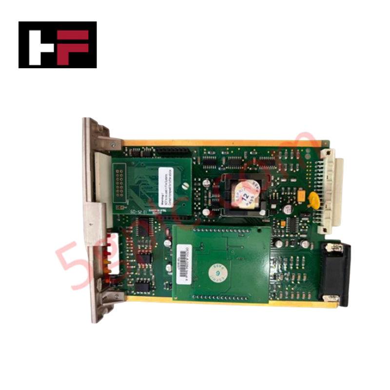
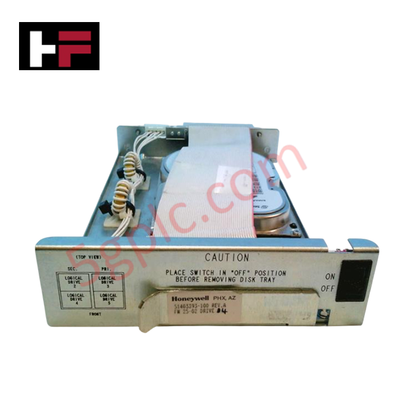
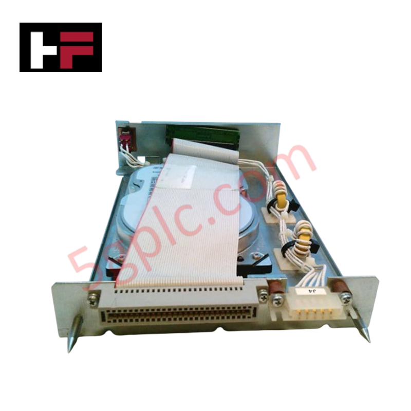
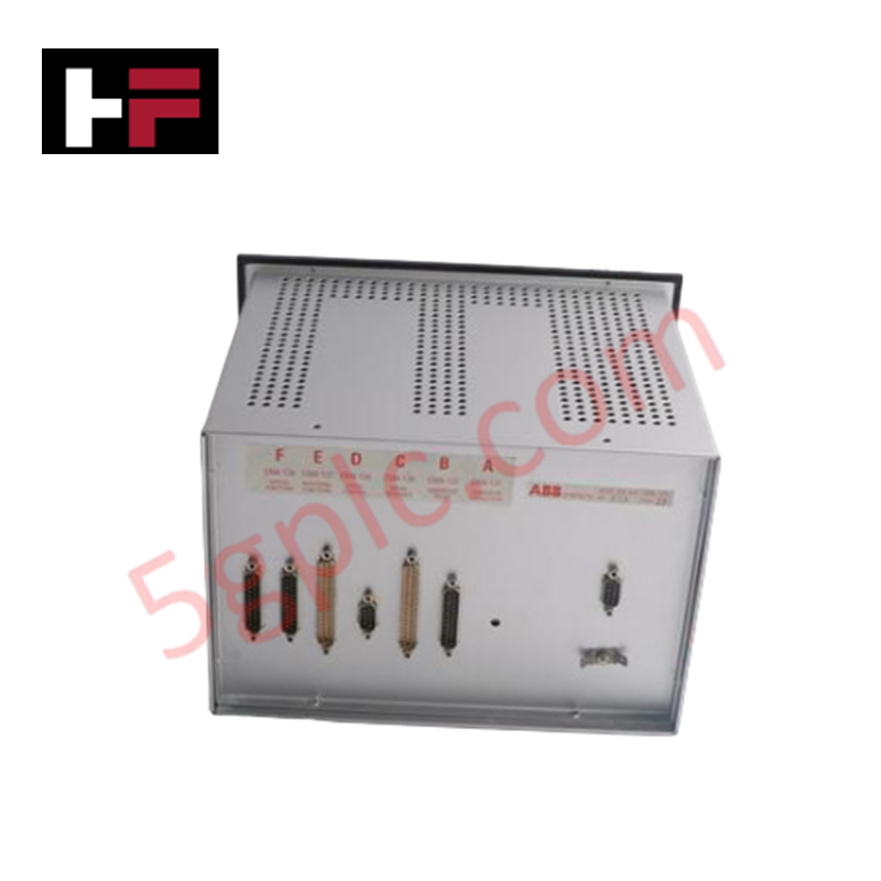
Configured for catalytic sensor excitation in Zellweger System 57 gas detection controllers, the Honeywell 05701-A-0284 (05701-A-0284 Sensor Drive Module) provides direct physical/electrical execution of sensor drive current and signal conditioning. The module maintains the necessary excitation parameters for catalytic sensing elements, ensuring valid concentration data transmission to the host controller within the System 57 platform.
Hardware Specifications
| Parameter | Specification |
|---|---|
| Model | 05701-A-0284 |
| Brand | Honeywell |
| Origin | USA |
| Weight | 1.2 kg |
| Dimensions | 200 mm x 100 mm x 50 mm |
| Operating Temp | -20 to 50 deg C |
| Power Consumption | 24 V DC |
| Sensor Type | Catalytic |
Channel-to-Channel Isolation
The 05701-A-0284 module employs channel-to-channel isolation architecture to protect the sensor signal path from common-mode voltage interference and ground potential shifts within the System 57 rack. This electrical separation is mandatory to maintain the sensitivity of the catalytic sensor and to ensure that signals are correctly processed by the 4-20 mA loop protocol without interference from adjacent control cards. Isolation barriers also function to prevent cross-talk between sensor loops, ensuring that detection threshold triggers are accurately mapped to the specific channel under surveillance.
Frequently Asked Questions
Q: Can the 05701-A-0284 be hot-swapped while the System 57 backplane is powered?
A: No. Any attempt to remove or install this module while the chassis is energized may induce electrical transients or damage the connector pins. The system must be de-energized prior to module handling.
Q: How is the excitation current verified after installation?
A: Post-installation, the excitation current must be checked via the central control unit's diagnostic interface to ensure it matches the specific requirements of the connected catalytic sensor.
Field Installation Guidelines
- Physical Mounting: Insert the module into the designated System 57 chassis slot. Align the module carefully with the rear connector to avoid pin damage. Secure the module using the built-in locking mechanism.
- Shielding and Grounding: Use shielded twisted-pair cabling for all sensor inputs. The shield must be connected to a clean earth ground at the cabinet entry to minimize the influence of electromagnetic noise on the catalytic bridge circuit.
- Wiring Separation: Route sensor inputs away from high-power AC lines, motor drives, and relay output cabling. Maintain a minimum separation of 150 mm to avoid induced signal fluctuations.
- Cable Termination: Ensure all terminals are tightened to the specified torque range. Poor electrical contact at the terminal block can lead to resistance variations in the catalytic bridge, resulting in sensor drift or false alarm states.
Additional Information
- 100% Genuine Parts: All products are original and authentic, ensuring reliable industrial performance.
- 30-Day Refund Guarantee: Return any in-stock item within 30 days in original, unopened packaging for a full refund (excluding shipping and fees).
- 12-Month Warranty: Covers defects in materials or workmanship; excludes misuse, normal wear, or unauthorized modifications.
- Worldwide Shipping: We ship via USPS, UPS, FedEx, and DHL. Delivery times vary by country and may be subject to customs or import fees.
- Support & Contact: Technical and warranty assistance is available anytime. Contact us here: Contact.
- Purchase Guidance: Check product specifications and compatibility carefully before ordering to ensure proper application.

Tech & Buying Guide

Why 24V DC Power Supplies Standardize Modern Industrial Automation
Industrial control cabinets worldwide rely on 24V DC as the universal power standard for field instrumentation, sensors, and controllers. Walk into any manufacturing plant, and you will find PLCs, human-machine interfaces (HMIs), and smart actuators running on extra-low voltage DC. Standardizing on 24V DC enhances operational safety, lowers cabinet footprint, and maintains steady control performance across factory networks.

Essential Motion Control Commands: A Practical Guide for Engineers
Automation engineers often rely on precise position and speed control to drive modern factory machinery. Modern industrial systems, such as Programmable Logic Controllers (PLCs) and Distributed Control Systems (DCS), depend heavily on standardized motion instructions. Mastering these commands ensures operational safety, protects mechanical components, and optimizes cycle times across production lines.

Mastering Modern Industrial Joystick Controls in Heavy Automation
Industrial joysticks play a pivotal role in human-machine interaction across heavy material handling and mobile hydraulics. These tactile controllers translate complex operator movements into precise electrical signals for PLCs, motion controllers, and DCS networks. Consequently, selecting and installing the right joystick architecture ensures operator safety, reduces fatigue, and optimizes equipment performance.