Understanding Marshalling Cabinets in Industrial Control Systems Architecture
- 〡
- 〡 by WUPAMBO

Industrial control system deployments rely on structured signal distribution to bridge field instrumentation with central processing hardware. A marshalling cabinet serves as the vital intermediate connection point between heavy field home-run multi-pair cables and delicate input/output (I/O) modules housed inside Programmable Logic Controller (PLC) or Distributed Control System (DCS) enclosures. By segregating field cable terminations from control hardware, engineers maintain system flexibility, safeguard controller components, and streamline commissioning workflows.
Primary Architectural Function of a Marshalling Cabinet
The primary function of a marshalling cabinet involves interfacing field multi-pair trunk cables with control system I/O assemblies. Field signals from sensors, valves, and transmitters route into field junction boxes before traveling through heavy home-run cables to the control room equipment area.
Inside the marshalling cabinet, technicians terminate field cable pairs onto designated terminal blocks. Cross-wiring routines or prefabricated cables then organize these raw signals into neat logical channels that match specific I/O cards inside the adjacent system cabinet.
Expert Insight: Physically separating field terminations from system control racks reduces physical disturbance to CPU components during maintenance. Field wiring modifications happen exclusively in the marshalling area, protecting sensitive system electronics from accidental short circuits or ESD damage.
Structural Typologies: Dedicated vs Combined Enclosure Designs
Automation engineers select from distinct cabinet architectures based on overall project scale and total I/O point density:
- Dedicated Marshalling Enclosure: Large process facilities utilize standalone marshalling cabinets separated from system cabinets. Integrators ship these cabinets to the site early, allowing technicians to land field cables while software engineers build the DCS racks.
- Combined System-Cum-Marshalling Cabinet: Smaller skid-mounted systems or packaged PLC units integrate controllers, I/O modules, power distribution, and field terminal blocks into a single footprint. This approach reduces panel costs but requires complete factory testing before site delivery.
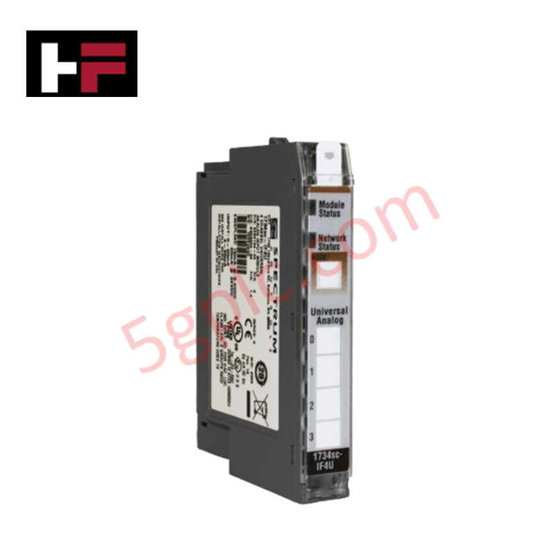
- Electronic Marshalling Architecture: Modern universal I/O technology routes field cables directly into configurable software-assigned modules. Electronic marshalling eliminates manual cross-wiring panels and reduces control room footprint requirements.
Comparative Architectural Overview of Cabinet Solutions
| Parameter | Dedicated Marshalling Cabinet | Combined System Enclosure | Electronic Marshalling Solution |
|---|---|---|---|
| System Footprint | Large (Requires separate enclosures) | Medium (Single integrated panel) | Compact (Minimal panel footprint) |
| Field Wiring Flexibility | High (Handled via physical cross-wiring) | Moderate (Limited terminal space) | Maximum (Software-configurable I/O mapping) |
| Deployment Phase | Early site delivery for field termination | Single-phase delivery after full assembly | Streamlined direct-to-card field landing |
| Component Density | Houses relays, barriers, isolators, terminals | Combines controllers, I/O, and barriers | Integrates intrinsic safety on smart I/O |
| Target Application | Large-scale DCS process facilities | Small PLC skids and packaged machinery | Modern flexible automation plants |
Preempting Common Testing and Commissioning Pitfalls
Field commissioning often encounters minor wiring errors that delay loop testing schedules. Project teams must execute strict QA checks during Factory Acceptance Testing (FAT) to prevent field downtime:
- Polarity Reversal: Verify positive and negative wire assignments for 4-20mA loop-powered analog transmitters.
- Shield Grounding Errors: Ensure instrument shield drain wires ground at the marshalling cabinet single point to avoid ground loops.
- Fuse and Relay Selection: Inspect active terminal fuse ratings and confirm relay coil voltages match interposing circuit requirements.
- Ferrule and Lug Quality: Inspect crimp integrity on field conductor ends to eliminate intermittent open-circuit faults.
Application Scenario: Offshore Platform Automation Upgrade
During a safety instrumented system migration on an offshore oil platform, engineers faced strict footprint constraints and tight installation windows:
- Design Phase: The project team implemented electronic marshalling enclosures to replace legacy cross-wire frames. This design choice cut total cabinet footprint requirements by 40 percent.
- Site Execution: Technicians landed multi-core cables directly onto universal I/O modules without re-routing individual pairs. Software engineers assigned channel types (analog input, digital output, or HART communication) digitally during commissioning, reducing total loop-check duration by three weeks.
Author Profile
Li Ming is a Principal Control Systems Architect with over 15 years of field experience designing DCS and PLC cabinet architectures for petro-chemical plants and power stations. He specializes in fieldbus integration, SIL-rated safety instrumented systems, and digital transformation in factory automation.
- Posted in:
- control system cabinet
- factory automation
- field termination
- instrumentation engineering
- PLC DCS integration