










Product Details
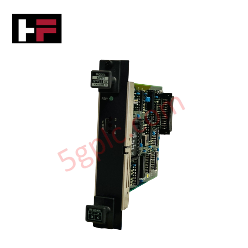
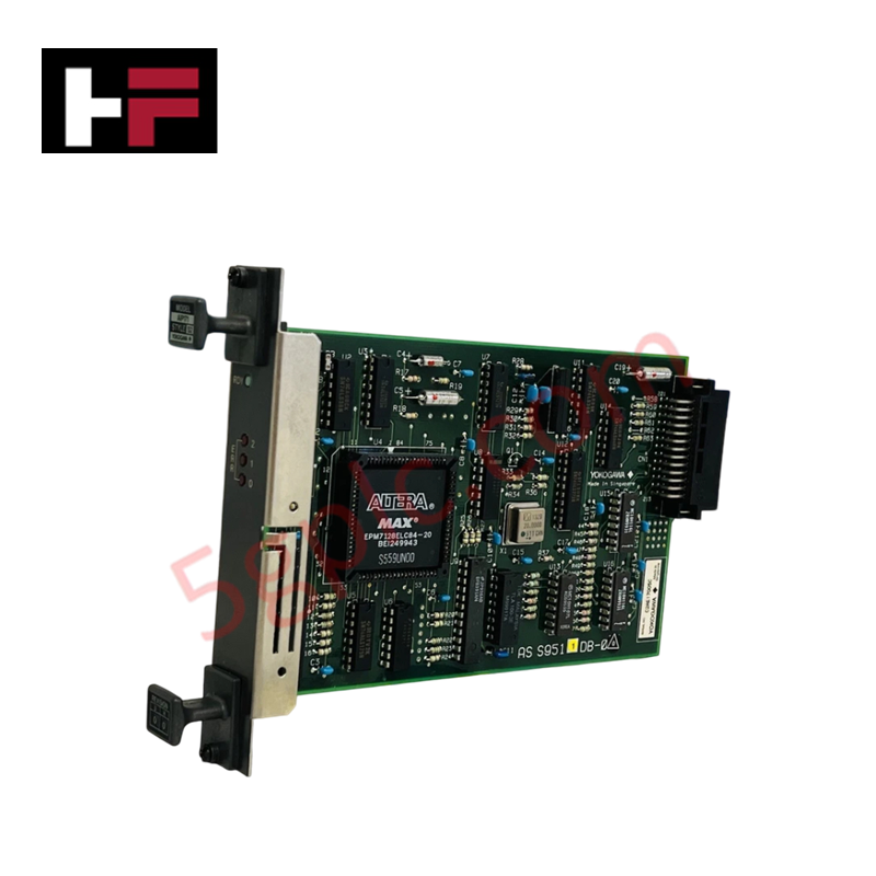
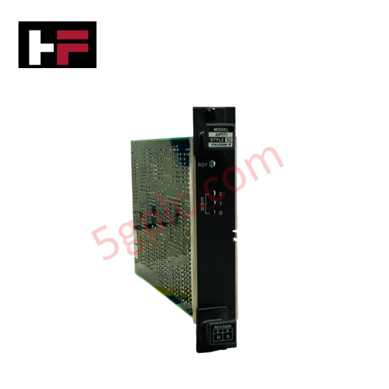
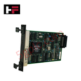
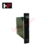
Configured for high-speed serial and Ethernet telemetry bridging in Yokogawa DCS architectures, the Yokogawa AIP171 S2 (AIP171 Transceiver Control Module) provides direct physical/electrical execution. It handles signal routing, interface protocol conversion, and deterministic data frame conditioning between local field network nodes and central processing racks across 24 VDC backplane segments.
Hardware Specifications
| Parameter | Specification |
|---|---|
| Model | AIP171 S2 |
| Brand | Yokogawa |
| Origin | Japan |
| Weight | 0.2 kg |
| Dimensions | 3.2 cm x 12 cm x 13 cm |
| Operating Temp | 0 to 50 deg C |
| Power Consumption | 20 W |
| Transceiver Frequency | 100 MHz to 6 GHz |
| Primary Voltage | 24 VDC |
| Network Interfaces | RS-485, RS-232, Ethernet |
| Bus Protocols | TCP/IP, SPI, I2C, UART |
Channel-to-Channel Isolation and Differential Signal Conditioning
The AIP171 S2 incorporates galvano-magnetic channel-to-channel isolation circuits designed to block earth potential loops and prevent high-voltage transient coupling into core backplane logic. Differential bus interfaces (RS-485/Ethernet) utilize balanced line transceivers to maintain high common-mode rejection ratios across noisy industrial environments. The module enforces strict signal conditioning protocols for incoming UART, I2C, and SPI frames, suppressing line impedance mismatches and electromagnetic interference before packet transmission to the DCS system bus.
Frequently Asked Questions
Q: Does the AIP171 S2 support online hot-swapping during active station operation?
A: Module replacement limits depend on the specific DCS rack backplane configuration; hot-swapping must be verified against backplane bus power allocation to avoid communication disruption on active serial buses.
Q: What power source supplies the 20 W operational requirement of the module?
A: The module draws power directly from the 24 VDC system power supply distribution bus integrated within the rack assembly.
Q: How does the module handle ground potential differences between remote RS-485 nodes?
A: Integrated channel-to-channel isolation barriers decouple signal reference grounds between isolated node ports, eliminating ground loop current flows.
Field Installation Guidelines
- ESD Safeguards: Always attach an anti-static wrist strap connected to a verified earth ground point prior to inserting or removing the transceiver card.
- Mechanical Insertion: Align the printed circuit board edge card with the chassis guide rails and push firmly until the backplane locking mechanism engages completely.
- Shield Grounding: Connect communications cable shields to the main instrument chassis ground terminal at a single end to prevent circulating ground currents.
- Wiring Separation: Route low-voltage communication cables (RS-485, Ethernet) in dedicated metallic conduits separated from high-voltage AC power lines.
Additional Information
- 100% Genuine Parts: All products are original and authentic, ensuring reliable industrial performance.
- 30-Day Refund Guarantee: Return any in-stock item within 30 days in original, unopened packaging for a full refund (excluding shipping and fees).
- 12-Month Warranty: Covers defects in materials or workmanship; excludes misuse, normal wear, or unauthorized modifications.
- Worldwide Shipping: We ship via USPS, UPS, FedEx, and DHL. Delivery times vary by country and may be subject to customs or import fees.
- Support & Contact: Technical and warranty assistance is available anytime. Contact us here: Contact.
- Purchase Guidance: Check product specifications and compatibility carefully before ordering to ensure proper application.


Tech & Buying Guide

Understanding Siemens PLC Memory Cards: MMC, SMC, and SD Solutions in Industrial Automation
Memory management plays a pivotal role in maintaining control system reliability across modern manufacturing plants. Industrial control systems rely on specialized memory cards to store project logic, firmware updates, and retentive system data. Siemens uses several memory architectures, including Micro Memory Cards (MMC) and SIMATIC Memory Cards (SMC). Engineers must understand these hardware variations to ensure zero data loss and minimize downtime during maintenance routines.

Redefining Control Systems: The Rise of Flexible I/O Modules in Industrial Automation
Conventional input-output architectures often limit engineering agility and inflate long-term inventory costs. Today, Flexible Input/Output Modules (FIOM) are transforming how control system engineers design, commission, and maintain automation infrastructure. By allowing individual channel software configuration, FIOM technology bridges the gap between rigid hardware design and dynamic plant requirements.

Understanding Modern SCADA Systems: Architecture, Communication Topologies, and Industrial Applications
Supervisory Control and Data Acquisition (SCADA) systems form the digital backbone of modern industrial automation. They collect critical field data, transmit signals across vast distances, and empower plant operators with real-time process visibility. Across modern infrastructures, SCADA solutions streamline centralized control and maintain continuous operational uptime.