


Product Details
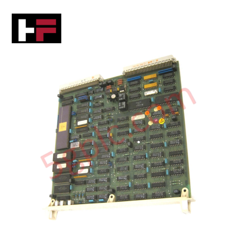
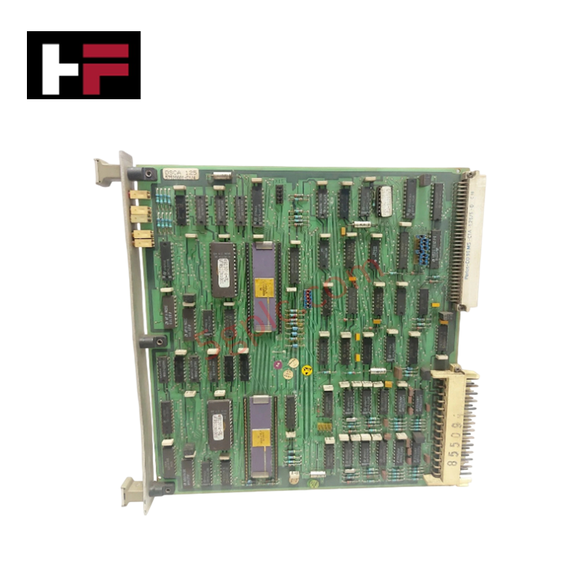
The ABB UNS 1860B-P V1 3BHB001336R0001, also cataloged as the UNS 1860B-P V1 Measuring Interface, operates as a dedicated hardware component for analog and digital channel processing within ABB control system platforms. The hardware accepts mixed field configurations, acquiring multi-range voltage, current, RTD, or thermocouple inputs alongside discrete 24 VDC signal tracking. It converts localized electrical potentials and microvolt thermal variances into digitized registers, isolating electrical noise paths across the active internal logic circuitry.
Hardware Specifications
| Parameter | Specification |
|---|---|
| Model | UNS 1860B-P V1 3BHB001336R0001 |
| Brand | ABB |
| Origin | Switzerland |
| Weight | 0.40 kg |
| Dimensions | 130 mm x 115 mm x 30 mm |
| Operating Temp | 0 to +60 deg C |
| Power Consumption | < 5 W |
| Power Supply | 24 VDC |
| Analog Inputs | 8 channels (Voltage, Current, RTD, TC) |
| Digital Channels | 8 channels (24 VDC sink/source) |
| Analog Input Accuracy | +/-0.1% of full scale |
| Digital Channel Rating | 2 A continuous, 10 kHz max frequency |
Profinet / EtherNet/IP Deterministic Networks and I/O Density Scaling
The internal data converters route the processed data arrays over backplane bus lines to interface with modern communication controllers. When integrating the module within Profinet / EtherNet/IP deterministic networks, system engineers must adjust transmission scheduling parameters to account for the high density of mixed analog and high-speed 10 kHz digital registers. Proper configuration eliminates synchronization dropouts on the bus, allowing stable I/O density scaling during real-time hardware execution scans.
Frequently Asked Questions
Q: What are the explicit hot-swap boundaries for the UNS 1860B-P V1 module?
A: This measuring interface is restricted from hot-swapping while the 24 VDC system power rail or active external analog loops are energized. Inserting or extracting the card during operation can introduce electrical transients that degrade calibration coefficients or disrupt adjacent modules.
Q: How is the channel architecture configured when mixing thermocouple and current loops on the same board?
A: Selection of signal type (voltage, current, RTD, TC) is performed via internal software registers and matching connection schemas on the terminal assembly. Shield paths must remain separated to maintain the +/-0.1% full scale input accuracy.
Field Installation Guidelines
Mount the unit vertically within an enclosure that minimizes particulate exposure and thermal accumulation. Bond the structural rail assembly to the central station earth reference using low-impedance conductors to maximize the efficiency of the built-in galvanic isolation components. Route low-voltage thermocouple and 4-20 mA current paths through dedicated, shielded channels, keeping them segregated from high-power alternating current switching wires to prevent inductive noise injection. Maintain specified clearance areas around the chassis profile to allow adequate passive thermal dissipation across the full operating range.
Additional Information
- 100% Genuine Parts: All products are original and authentic, ensuring reliable industrial performance.
- 30-Day Refund Guarantee: Return any in-stock item within 30 days in original, unopened packaging for a full refund (excluding shipping and fees).
- 12-Month Warranty: Covers defects in materials or workmanship; excludes misuse, normal wear, or unauthorized modifications.
- Worldwide Shipping: We ship via USPS, UPS, FedEx, and DHL. Delivery times vary by country and may be subject to customs or import fees.
- Support & Contact: Technical and warranty assistance is available anytime. Contact us here: Contact.
- Purchase Guidance: Check product specifications and compatibility carefully before ordering to ensure proper application.
Tech & Buying Guide

Core Components of Programmable Logic Controllers (PLC) in Industrial Automation
A Programmable Logic Controller (PLC) serves as the digital backbone of modern factory automation. Whether you are managing complex assembly lines or simple process loops, understanding the hardware and software architecture of a PLC is essential for any control systems engineer.

PLC vs. PC: Navigating the Architectural Differences in Industrial Automation
In the realm of factory automation, professionals often debate the roles of Programmable Logic Controllers (PLCs) and Personal Computers (PCs). While both devices share fundamental computing architectures—including a processor, memory, and an operating system—their design philosophies diverge significantly. Understanding these distinctions is critical for selecting the right hardware for your industrial control systems.

Essential SCADA Features for Modern IoT-Enabled Industrial Automation
The convergence of traditional SCADA systems with the Industrial Internet of Things (IIoT) has redefined factory automation. Choosing a robust platform requires more than just standard monitoring capabilities. In this era of Industry 4.0, your supervisory system must bridge the gap between legacy control systems and enterprise-level data integration.