


Product Details
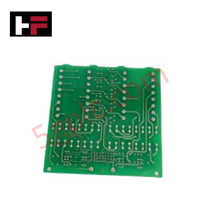
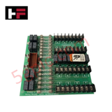
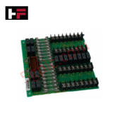
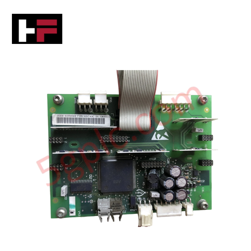
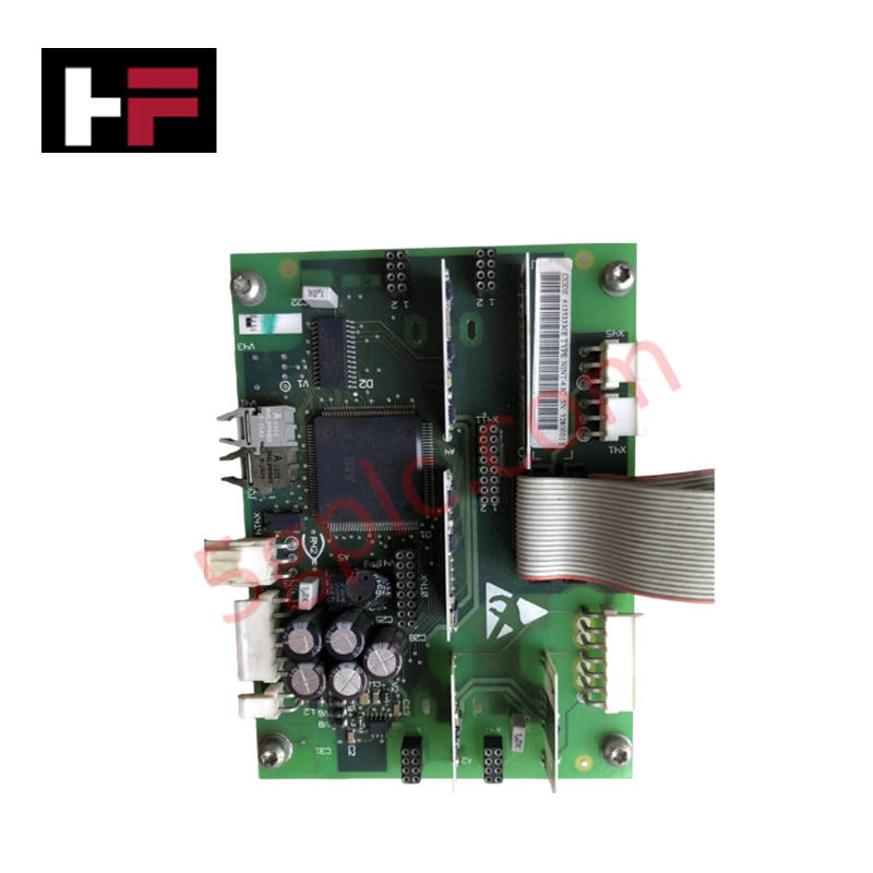
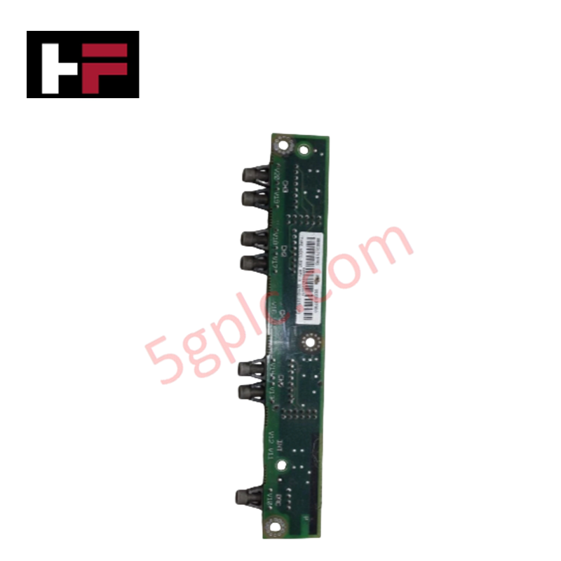
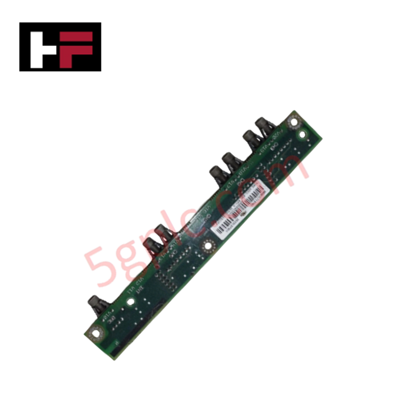
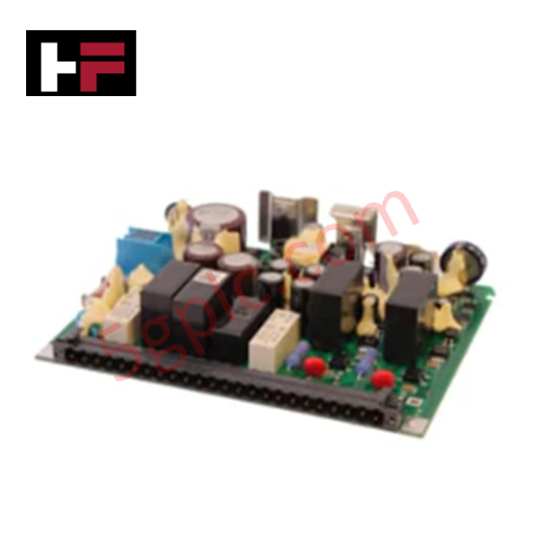
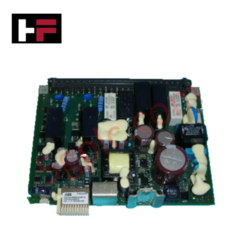
Configured for high-speed digital I/O routing in Bailey control loops, the ABB NTRO02-A (NTRO02-A Relay Output Board) provides direct physical/electrical execution.
Hardware Specifications
| Parameter | Specification |
|---|---|
| Model | NTRO02-A |
| Brand | ABB |
| Origin | USA / Europe standard sourcing |
| Weight | 0.1 kg |
| Dimensions | 100 mm x 60 mm x 25 mm |
| Operating Temp | -20 to +60 deg C |
| Power Consumption | 2 mA nominal input current draw |
| Channels | 16 independent digital output channels |
| Input / Output Voltage Range | 12 to 32 VDC |
| Continuous Output Current | 200 mA per channel maximum |
| Channel-to-Channel Isolation | 2500 VDC optical isolation barriers |
| Diagnostics | Dedicated LED status indicators per channel |
| Product Type | Digital Output Cards |
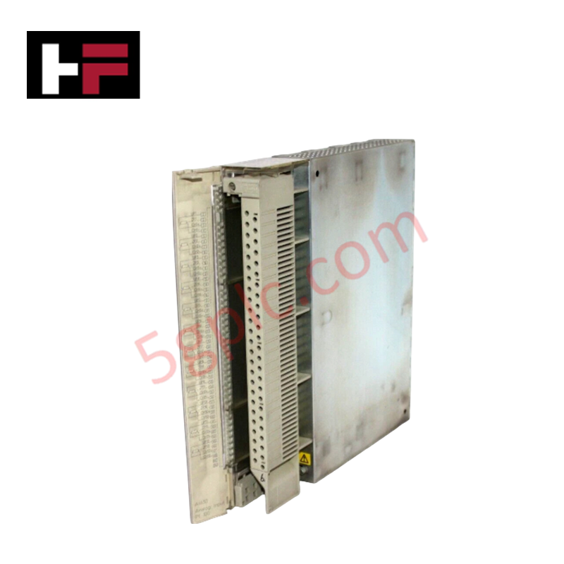
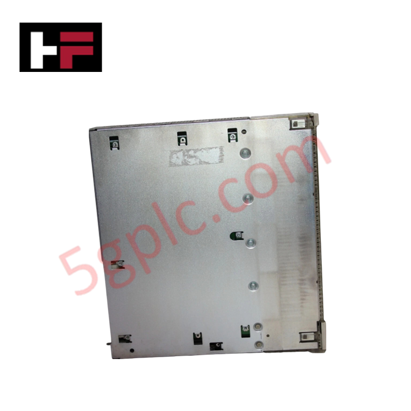
I/O Density Scaling and Backplane Flash Compatibility
The ABB NTRO02-A manages multi-channel switching loops while matching continuous I/O density scaling demands within the master enclosure array. Optical isolation structures rated at 2500 VDC separate individual electrical field circuits to eliminate ground loop distortion and prevent induction noise from corrupting data paths across the backplane bus. The hardware timing matrix supports synchronized interaction over Profinet / EtherNet/IP deterministic networks, maintaining operational status updates alongside standard system components without modifying firmware flash compatibility baselines.
Frequently Asked Questions
Q: Does the NTRO02-A hardware assembly support live online extraction (hot-swap)?
A: No. The board utilizes direct terminal and edge-connector points without solid-state current limiting switches. Upstream power feeds to both the module rack and field-side circuits must be disconnected before board insertion or removal to prevent damage to the optical components.
Q: How do the embedded LED indicators assist in troubleshooting physical loop failures?
A: Each of the 16 paths features a logic-side LED indicator that illuminates when the internal gating circuit energizes the corresponding channel output, allowing field engineers to visually cross-reference processing logic states against field-side voltage execution.
Field Installation Guidelines
- Mount the relay output board securely into its specified subrack slot or carrier base inside the electrical cabinet enclosure.
- Establish clean wiring connections to the terminal block using properly stripped conductor leads matching the 12 to 32 VDC working voltage parameters.
- Route field wiring pathways separate from heavy AC power cables or electric motor motor drives to prevent EMI coupling onto the 200 mA output lines.
- Verify the integrity of the common ground return path to ensure that the 2500 VDC optical isolation barrier performs as specified under surge conditions.
Additional Information
- 100% Genuine Parts: All products are original and authentic, ensuring reliable industrial performance.
- 30-Day Refund Guarantee: Return any in-stock item within 30 days in original, unopened packaging for a full refund (excluding shipping and fees).
- 12-Month Warranty: Covers defects in materials or workmanship; excludes misuse, normal wear, or unauthorized modifications.
- Worldwide Shipping: We ship via USPS, UPS, FedEx, and DHL. Delivery times vary by country and may be subject to customs or import fees.
- Support & Contact: Technical and warranty assistance is available anytime. Contact us here: Contact.
- Purchase Guidance: Check product specifications and compatibility carefully before ordering to ensure proper application.
Tech & Buying Guide

Industrial PC vs. Commercial PC: Selecting the Right Hardware for Automation
In the demanding world of factory automation, selecting the correct computing platform is critical for system reliability. While commercial PCs power our daily lives, they often fail when subjected to the harsh realities of the production floor. Understanding the fundamental differences between an Industrial PC (IPC) and a standard office PC helps engineers optimize control systems for longevity and performance.

Core Components of Programmable Logic Controllers (PLC) in Industrial Automation
A Programmable Logic Controller (PLC) serves as the digital backbone of modern factory automation. Whether you are managing complex assembly lines or simple process loops, understanding the hardware and software architecture of a PLC is essential for any control systems engineer.

PLC vs. PC: Navigating the Architectural Differences in Industrial Automation
In the realm of factory automation, professionals often debate the roles of Programmable Logic Controllers (PLCs) and Personal Computers (PCs). While both devices share fundamental computing architectures—including a processor, memory, and an operating system—their design philosophies diverge significantly. Understanding these distinctions is critical for selecting the right hardware for your industrial control systems.