










Product Details
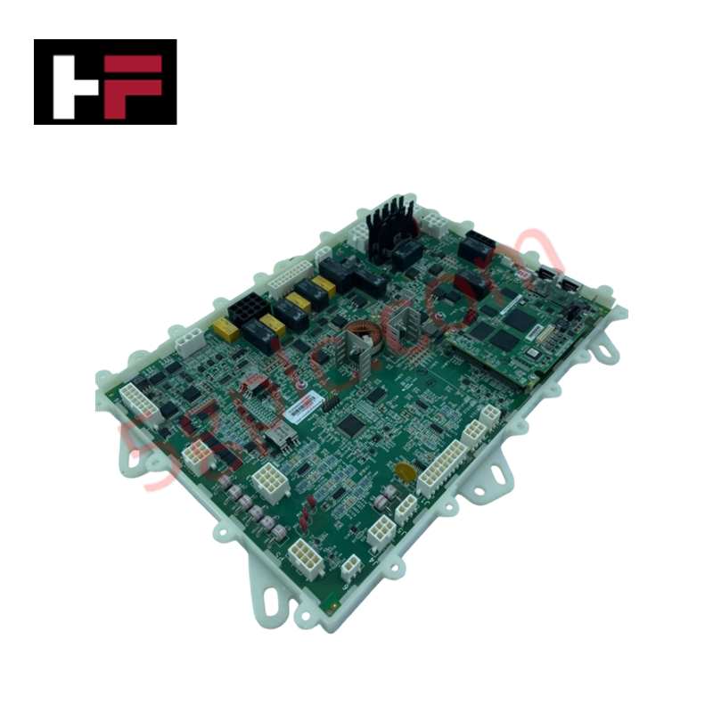
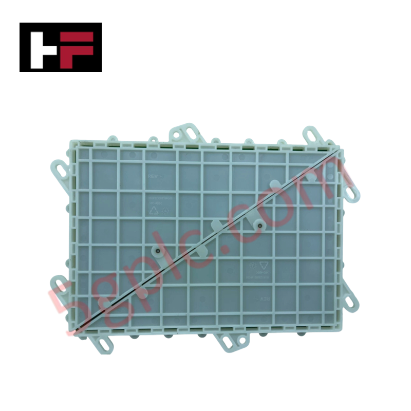
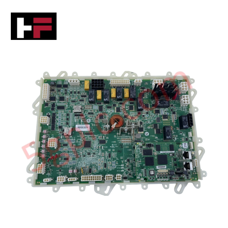
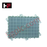
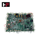
Configured for power distribution and auxiliary signal processing in GE Innovation Series drive platforms, the GE IS200AEPAH1BEB (IS200AEPA Circuit Board) provides direct physical/electrical execution.
Hardware Specifications
| Parameter | Specification |
|---|---|
| Model | IS200AEPAH1BEB |
| Brand | General Electric |
| Origin | USA |
| Weight | 0.85 kg |
| Dimensions | 280 x 210 x 40 mm |
| Operating Temp | 0 to 60 deg C |
| Power Consumption | 12 W |
| Board Series | Innovation Series Drive Control |
| Functional Acronym | AEPA |
| Revision Grade | Revision H1BEB |
| Board Coating | Conformal Coating |
| Interconnect Types | Multi-pin edge connectors, pluggable ribbon connectors |
Backplane Bus Communication Velocity and Firmware Flash Compatibility
The IS200AEPAH1BEB processes internal control signals across dedicated drive backplane assemblies. Onboard logic circuits and interface relays maintain high-speed signal routing to ensure backplane bus communication velocity across real-time motor control loops. The card provides native firmware flash compatibility across host GE Innovation Series rack configurations, allowing synchronized processing without manual firmware adjustments. Integrated test points and isolation barriers shield delicate low-voltage logic from power-stage transient surges.
Frequently Asked Questions
Q: How is the IS200AEPAH1BEB card physically secured within the drive assembly?
A: The card mounts directly into card cage guide slots and secures via retaining screws along its front edge bracket to maintain earth grounding and vibration stability.
Q: Are there onboard test points available for hardware diagnostics?
A: Yes, accessible surface test points (TP) allow technicians to measure internal power rail voltages and verify control signal state integrity directly.
Q: What precautions should be taken regarding static handling?
A: Always connect a grounded ESD wrist strap to the enclosure frame before touching card surfaces to protect onboard integrated circuits and surface-mount components.
Field Installation Guidelines
Isolate all main power feeds and control voltages supplying the drive rack prior to performing maintenance. Attach a calibrated ESD grounding strap to unpainted cabinet steel to prevent electrostatic discharge during module swap-out. Align the card edges with the enclosure mounting tracks, push firmly until the multi-pin backplane connectors fully seat, and torque retaining screws hand-tight. Ensure all ribbon cables and wiring harness plugs are locked into place before restoring system power.
Additional Information
- 100% Genuine Parts: All products are original and authentic, ensuring reliable industrial performance.
- 30-Day Refund Guarantee: Return any in-stock item within 30 days in original, unopened packaging for a full refund (excluding shipping and fees).
- 12-Month Warranty: Covers defects in materials or workmanship; excludes misuse, normal wear, or unauthorized modifications.
- Worldwide Shipping: We ship via USPS, UPS, FedEx, and DHL. Delivery times vary by country and may be subject to customs or import fees.
- Support & Contact: Technical and warranty assistance is available anytime. Contact us here: Contact.
- Purchase Guidance: Check product specifications and compatibility carefully before ordering to ensure proper application.




Tech & Buying Guide

Mastering the Siemens PLC Scan Cycle: How the CPU Executes Automation Programs
Industrial automation relies heavily on programmable logic controllers (PLCs) to manage complex manufacturing processes. Many engineers dive straight into programming without mastering the underlying architecture. However, understanding how a PLC CPU executes a program ensures reliable system design. Therefore, mastering the scan cycle optimizes both performance and troubleshooting in modern control systems.

How to Connect to Siemens S7 PLCs: 5 Essential Communication Methods
Establishing a reliable hardware link between a programming terminal and a Siemens SIMATIC controller is essential for engineering workflows. Field engineers rely on distinct physical layers, ranging from legacy serial connections to high-speed Industrial Ethernet protocols. Modern factory automation environments prioritize fast data transfer and seamless driver integration. Selecting the correct connection method simplifies program downloads, online monitoring, and system troubleshooting in complex control systems.

Will PLCs Become Obsolete? The Future of Control Systems in Industry 4.0
Modern manufacturing is undergoing a rapid technological transformation driven by Industry 4.0 innovations. Technologies like Artificial Intelligence (AI), Machine Learning (ML), and the Industrial Internet of Things (IIoT) are dominating discussions across the factory automation sector. Consequently, many engineers wonder if these advanced digital tools will eventually replace traditional Programmable Logic Controllers (PLCs). However, evaluating the core physics of industrial operations reveals a very different reality for control systems.