












Product Details
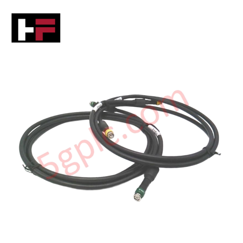
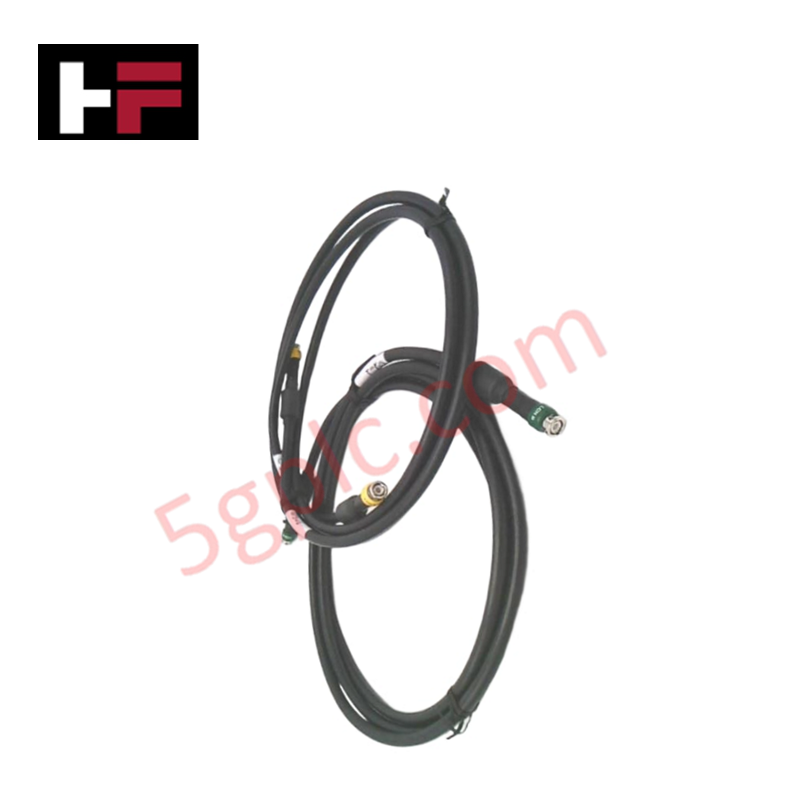
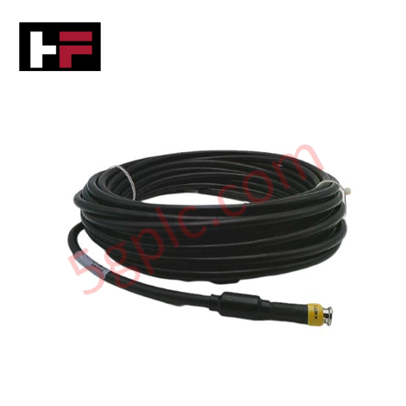
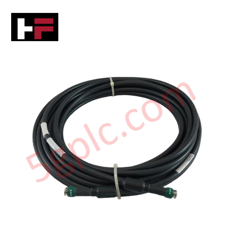
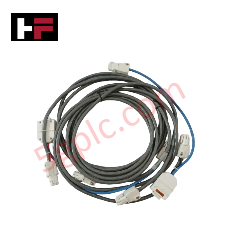
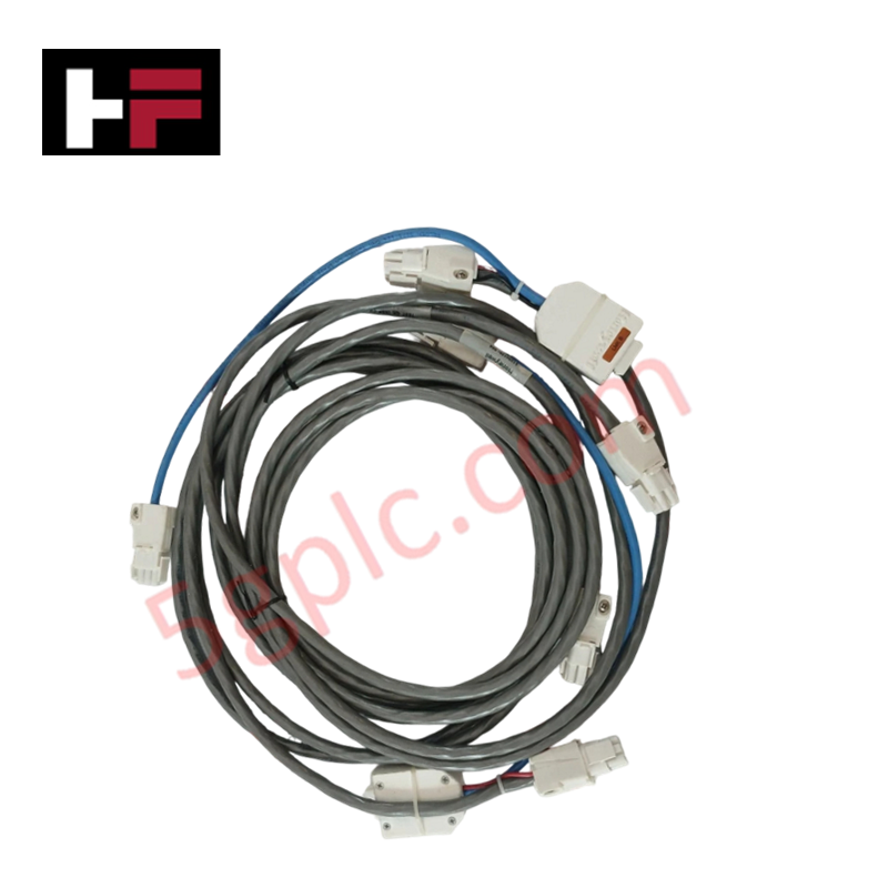
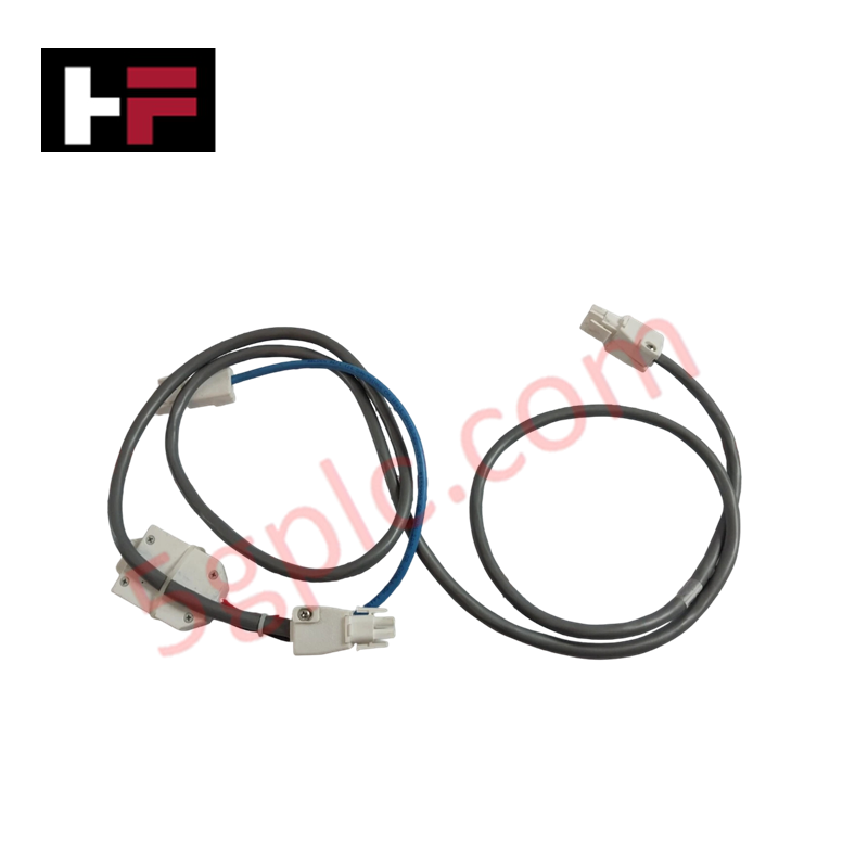
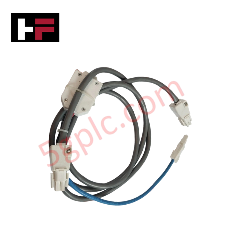
The Honeywell 51308112-003, also cataloged as the 51308112-003 Coaxial Cable Assembly, operates as a dedicated hardware component for high-speed Local Control Network (LCN) node interconnectivity within Honeywell TDC 3000 DCS platforms. Constructed as a 3 meter RG11 coaxial cable pair with pre-installed inline ferrite cores, the cable set establishes redundant physical layer links between network interface modules. The RG11 assembly maintains controlled characteristic impedance to minimize signal attenuation and high-frequency noise reflections across local control bus spans.
Hardware Specifications
| Parameter | Specification |
|---|---|
| Model | 51308112-003 |
| Brand | Honeywell |
| Origin | USA |
| Weight | 2.01 lbs (0.91 kg) |
| Dimensions | Cable Length: 3 meters (9.84 ft) |
| Operating Temp | 0 to 60 deg C |
| Power Consumption | Passive Interconnect Assembly |
| Cable Specification | RG11 Coaxial with Inline Ferrite Cores |
| Set Quantity | Set of 2 cables (Redundant Link Pair) |
| Core Application | Connecting Local Control Network (LCN) Nodes |
| Cable Impedance | 75 Ohm nominal |
Channel-to-Channel Isolation
The 51308112-003 RG11 coaxial cable set utilizes heavy braid and foil shielding around each conductor to prevent RF interference and cross-talk between redundant LCN A and LCN B network channels. Integrated inline ferrite beads suppress common-mode electromagnetic noise and high-frequency voltage transients before signals reach transceiver electronics on the network interface cards. This physical and electrical isolation preserves low-error bit transmission across active control node connections.
Frequently Asked Questions
Q: Can an individual cable in the 51308112-003 dual set be disconnected while the LCN network is operational?
A: Disconnecting one cable breaks communication on that specific link channel (A or B), but the network maintains operational node connectivity via the secondary redundant cable.
Q: What is the primary purpose of the inline ferrite cores on this RG11 coaxial assembly?
A: The ferrite cores act as high-frequency chokes to attenuate common-mode noise and electromagnetic interference picked up along the 3 meter cable run.
Q: What installation precautions prevent physical degradation of the RG11 coaxial cable structure?
A: Maintain the manufacturer specified minimum bend radius during cabinet routing to avoid deforming the dielectric core or damaging the outer shield braid.
Field Installation Guidelines
- Inspect the 3 meter cable jacket, BNC/F-type connectors, and ferrite modules for physical damage before installation.
- Route Link A and Link B coaxial cables through distinct cabinet paths to preserve physical redundancy and prevent concurrent mechanical damage.
- Align the coaxial connectors with the LCN node interface ports and twist to lock firmly into position.
- Ensure connector shield shells establish full 360-degree contact with the mating jack for ground continuity.
- Avoid overtightening or sharp bends near the connector terminations to prevent internal impedance mismatches.
Additional Information
- 100% Genuine Parts: All products are original and authentic, ensuring reliable industrial performance.
- 30-Day Refund Guarantee: Return any in-stock item within 30 days in original, unopened packaging for a full refund (excluding shipping and fees).
- 12-Month Warranty: Covers defects in materials or workmanship; excludes misuse, normal wear, or unauthorized modifications.
- Worldwide Shipping: We ship via USPS, UPS, FedEx, and DHL. Delivery times vary by country and may be subject to customs or import fees.
- Support & Contact: Technical and warranty assistance is available anytime. Contact us here: Contact.
- Purchase Guidance: Check product specifications and compatibility carefully before ordering to ensure proper application.
Tech & Buying Guide

DCS Commissioning Steps in Industrial Automation Projects
Commissioning a Distributed Control System (DCS) represents a crucial milestone when deploying modern process automation infrastructure. Field engineers must execute systematic verification steps to transition complex control hardware from static installation to dynamic plant control. Proper commissioning ensures that controllers, I/O modules, network switches, and HMI software operate in strict compliance with engineering design specifications before introducing live process fluids.

PLC and DCS Control System Spares Strategy: Engineering Guidelines
Modern factory automation relies on high-speed fiber optic backbones to link distributed control systems across noise-intensive industrial environments. Unlike copper wiring, optical fibers transmit data via light pulses, making them completely immune to electromagnetic interference (EMI). Field engineers must master optical cable joining and fusion splicing techniques to guarantee low-loss data transmission across critical Programmable Logic Controller (PLC) and Distributed Control System (DCS) nodes.

PLC and DCS Control System Spares Strategy: Engineering Guidelines
Industrial automation lifecycle management requires robust spare parts planning for Programmable Logic Controller (PLC) and Distributed Control System (DCS) platforms. Plant engineers must correctly categorize spare components during front-end engineering design to maintain high system availability. Miscalculating spare requirements can lead to prolonged unscheduled downtime, project budget overruns, or delayed site commissioning.