












Product Details
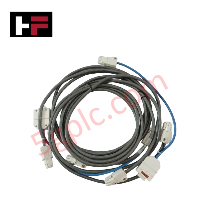
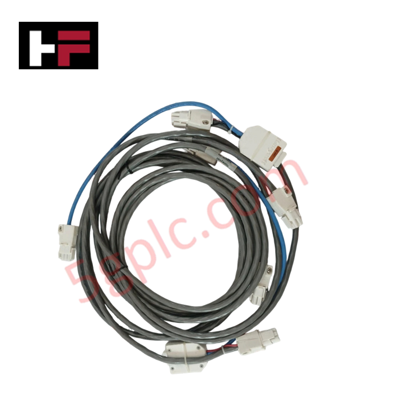
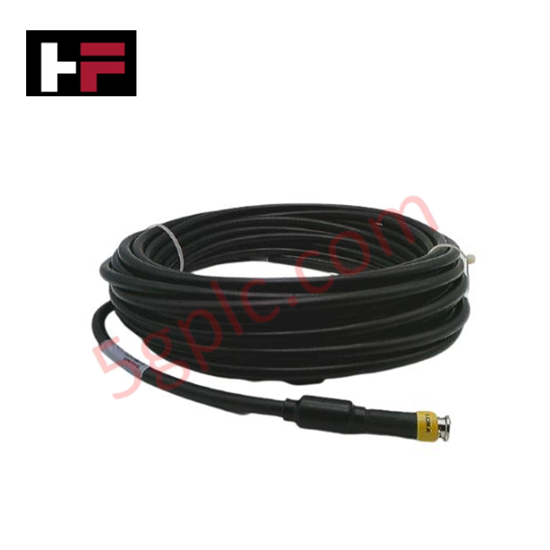
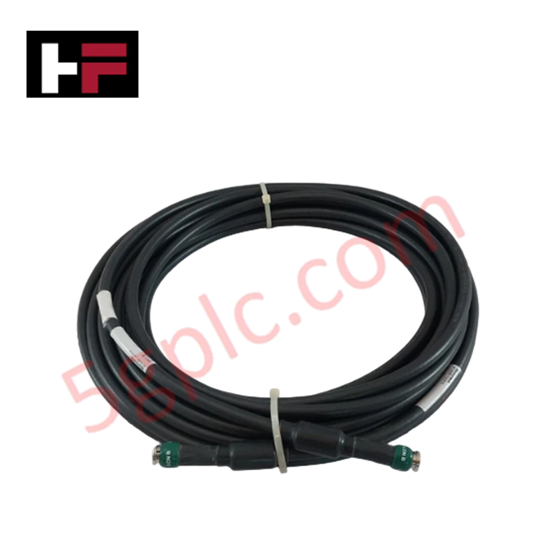
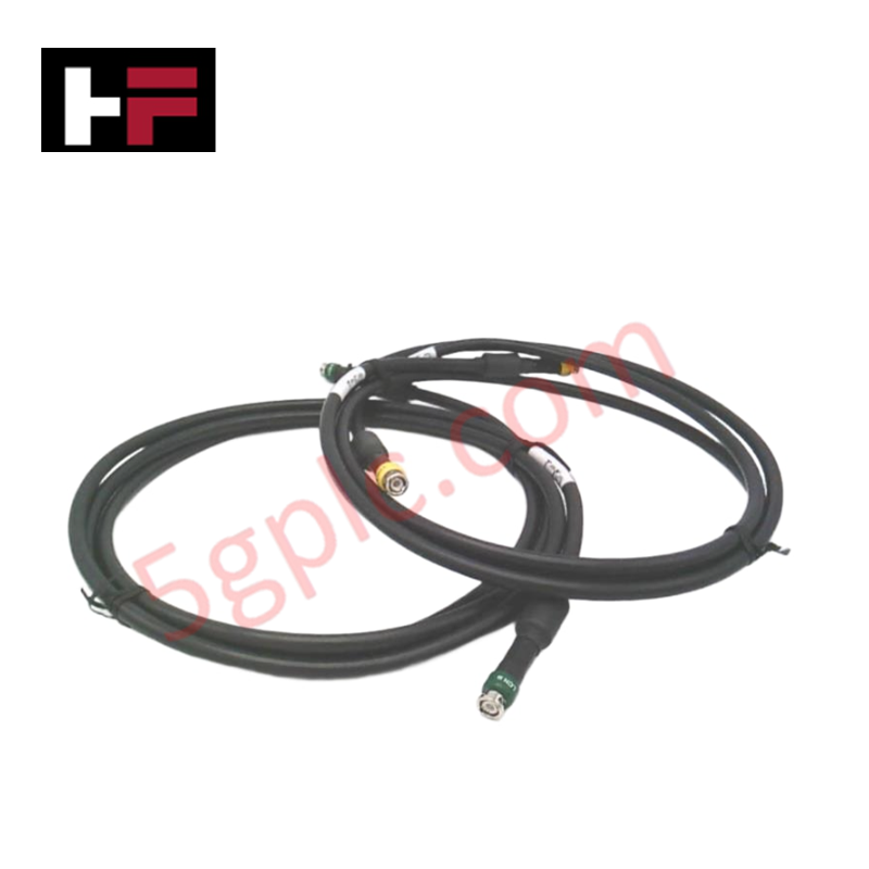
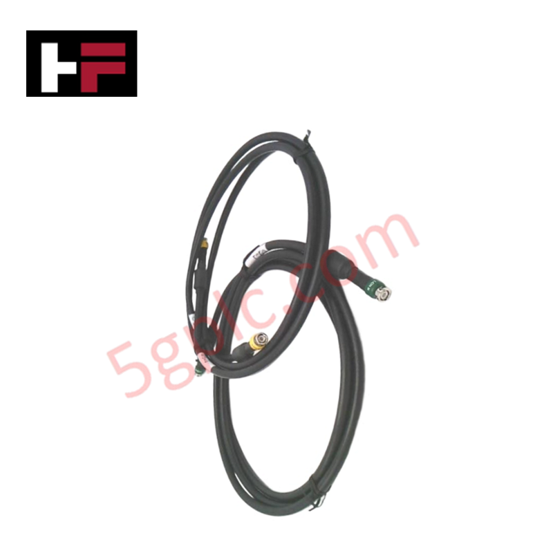
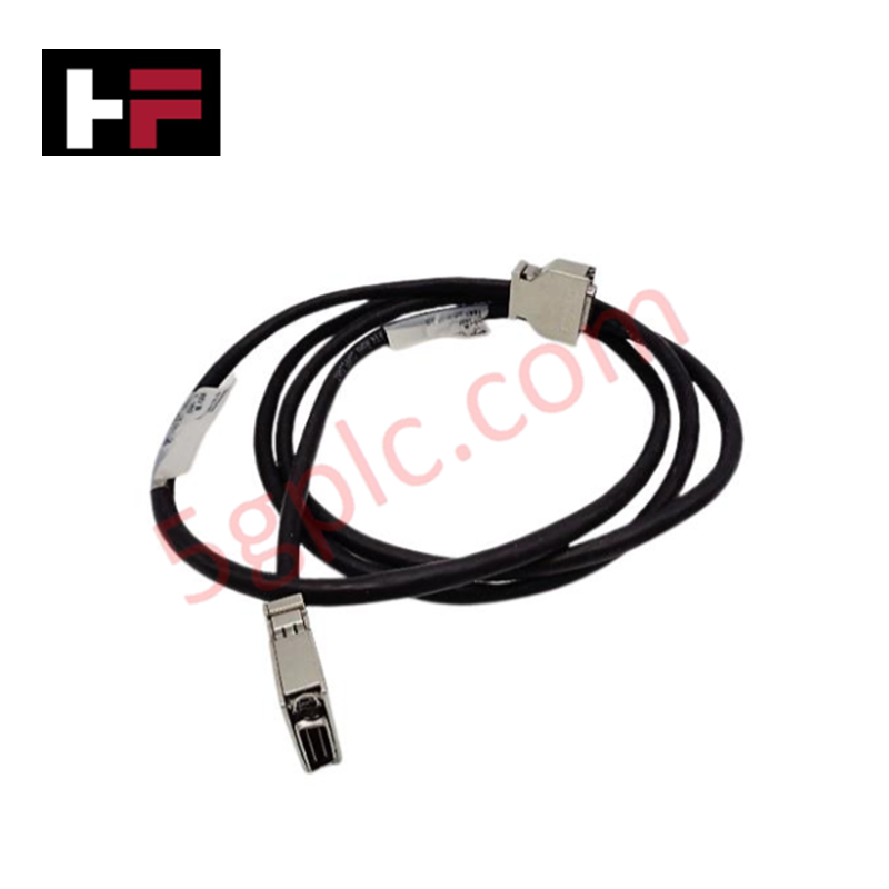
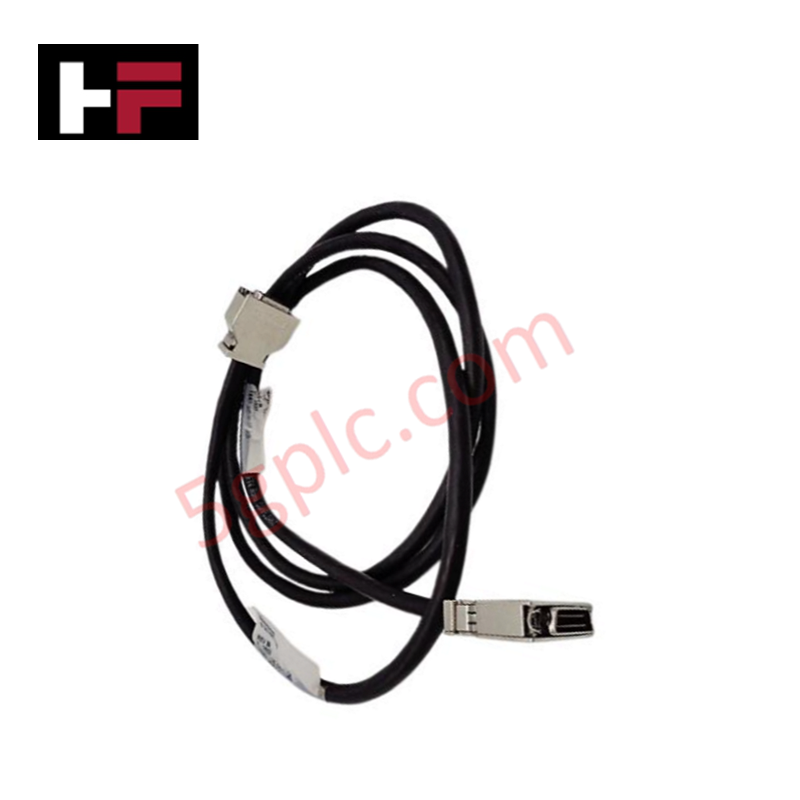
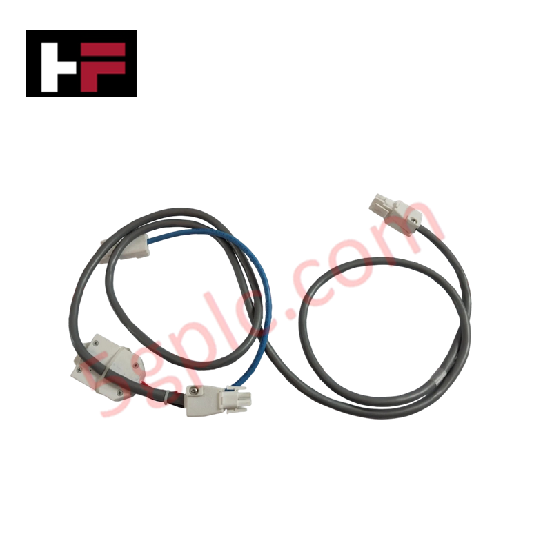
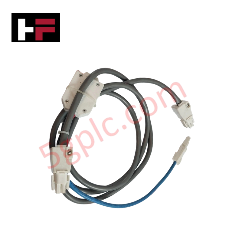
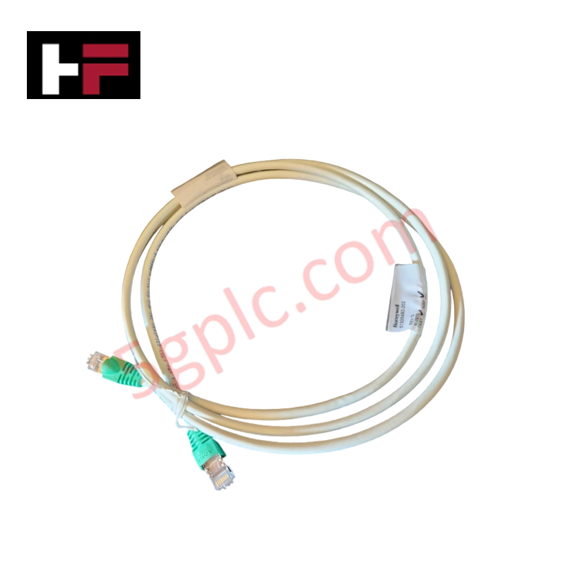
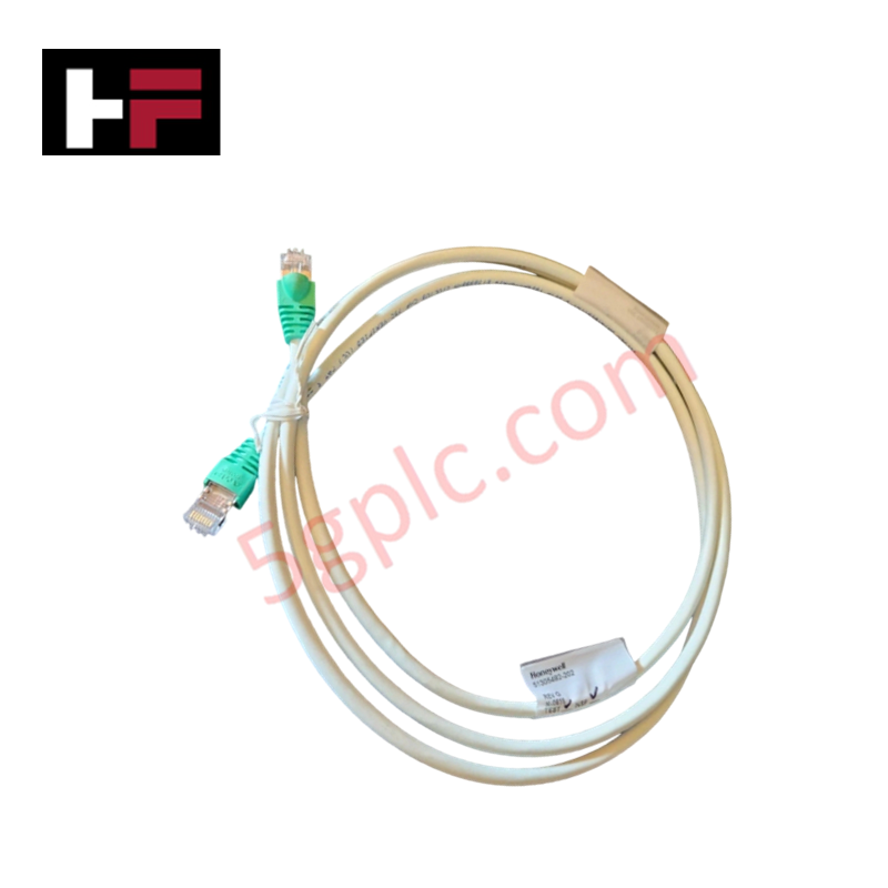
The Honeywell 51204126-004, also cataloged as the 51204126-004 Power I/O Link Cable with Protector Module, operates as a dedicated hardware component for dual-redundant I/O link signal interconnectivity and power distribution within Honeywell TDC 3000 networks. Configured as a 2-cable set spanning 4 meters with redundant Link A and Link B conductors, the assembly interfaces directly between process manager cards and sub-file backplanes to carry low-voltage logic signaling and system power rails. Integrated protector modules suppress line transients and isolate field-side disturbances along the serial communication bus.
Hardware Specifications
| Parameter | Specification |
|---|---|
| Model | 51204126-004 |
| Brand | Honeywell |
| Origin | USA |
| Weight | 2.70 lbs (1.22 kg) |
| Dimensions | Cable Length: 4 meters (13.12 ft) |
| Operating Temp | 0 to 60 deg C |
| Power Consumption | Passive Interconnect Assembly |
| Product Type | Power I/O Link Cable with Protector Module |
| Set Configuration | Includes 2 cables (Link A and Link B) |
| System Compatibility | Honeywell TDC 3000 |
| Mounting Type | Rack or panel installation |
Channel-to-Channel Isolation
The 51204126-004 interconnect assembly incorporates channel-to-channel isolation barriers between parallel Link A and Link B data paths to maintain dual-redundant link integrity. Grounded conductive shielding around each 4 meter cable run prevents signal cross-talk between high-speed serial I/O communication pairs and adjacent DC power distribution lines. Integrated surge and protection circuitry limits common-mode voltage spikes, shielding TDC 3000 backplane logic against ground potential displacement across rack frames.
Frequently Asked Questions
Q: Can an individual cable in the 51204126-004 set be disconnected while the TDC 3000 node remains online?
A: Yes, provided the system is operating in active dual-link redundancy. Disconnecting one cable (Link A or Link B) allows single-channel maintenance while the alternate link sustains uninterrupted backplane data transmission.
Q: What function does the integrated protector module perform on this cable assembly?
A: The protector module incorporates inline clamping components to attenuate voltage surges and high-frequency noise transients before they enter sensitive I/O card transceivers.
Q: How is chassis ground continuity established for the 4 meter cable shielding?
A: Metallic connector backshells establish direct contact with grounded enclosure panels or rack frame chassis terminals upon physical connection.
Field Installation Guidelines
- Power down connected rack sub-files before installing or replacing the 51204126-004 cable set in non-redundant configurations.
- Route Link A and Link B cables through separate cabinet wireways where possible to preserve physical channel segregation.
- Align connector pins with the corresponding TDC 3000 card file ports, pressing firmly until locking screws or retention latches engage fully.
- Maintain a minimum bend radius along the 4 meter cable length to avoid internal conductor fatigue and shielding deformation.
- Verify low-impedance ground bonding between cable shield terminals and the main enclosure earth ground bus.
Additional Information
- 100% Genuine Parts: All products are original and authentic, ensuring reliable industrial performance.
- 30-Day Refund Guarantee: Return any in-stock item within 30 days in original, unopened packaging for a full refund (excluding shipping and fees).
- 12-Month Warranty: Covers defects in materials or workmanship; excludes misuse, normal wear, or unauthorized modifications.
- Worldwide Shipping: We ship via USPS, UPS, FedEx, and DHL. Delivery times vary by country and may be subject to customs or import fees.
- Support & Contact: Technical and warranty assistance is available anytime. Contact us here: Contact.
- Purchase Guidance: Check product specifications and compatibility carefully before ordering to ensure proper application.
Tech & Buying Guide

DCS Commissioning Steps in Industrial Automation Projects
Commissioning a Distributed Control System (DCS) represents a crucial milestone when deploying modern process automation infrastructure. Field engineers must execute systematic verification steps to transition complex control hardware from static installation to dynamic plant control. Proper commissioning ensures that controllers, I/O modules, network switches, and HMI software operate in strict compliance with engineering design specifications before introducing live process fluids.

PLC and DCS Control System Spares Strategy: Engineering Guidelines
Modern factory automation relies on high-speed fiber optic backbones to link distributed control systems across noise-intensive industrial environments. Unlike copper wiring, optical fibers transmit data via light pulses, making them completely immune to electromagnetic interference (EMI). Field engineers must master optical cable joining and fusion splicing techniques to guarantee low-loss data transmission across critical Programmable Logic Controller (PLC) and Distributed Control System (DCS) nodes.

PLC and DCS Control System Spares Strategy: Engineering Guidelines
Industrial automation lifecycle management requires robust spare parts planning for Programmable Logic Controller (PLC) and Distributed Control System (DCS) platforms. Plant engineers must correctly categorize spare components during front-end engineering design to maintain high system availability. Miscalculating spare requirements can lead to prolonged unscheduled downtime, project budget overruns, or delayed site commissioning.