










Product Details
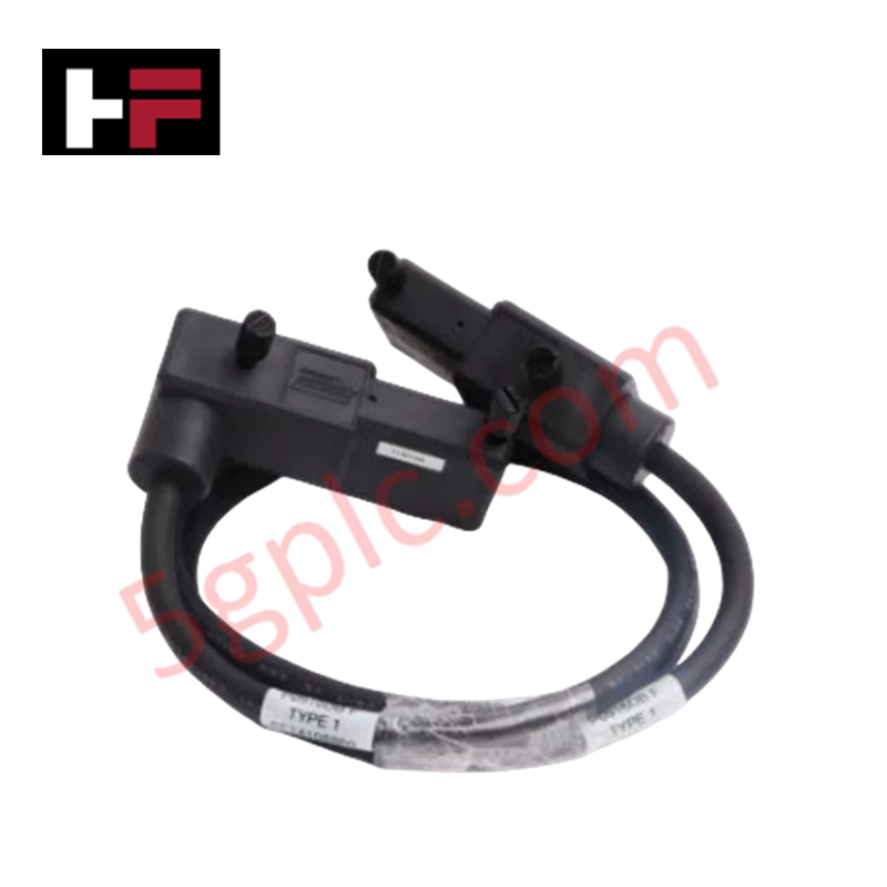
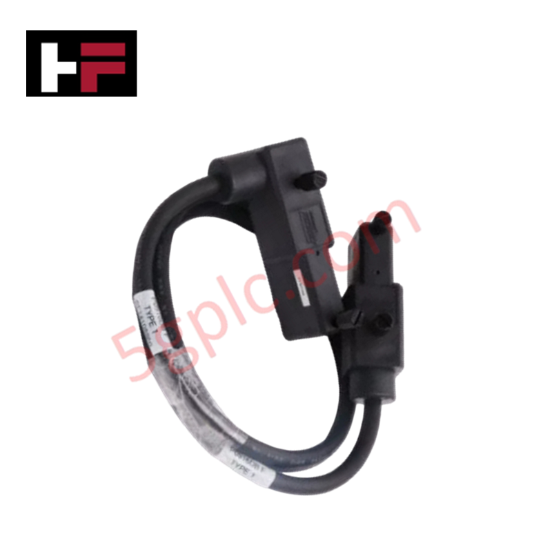
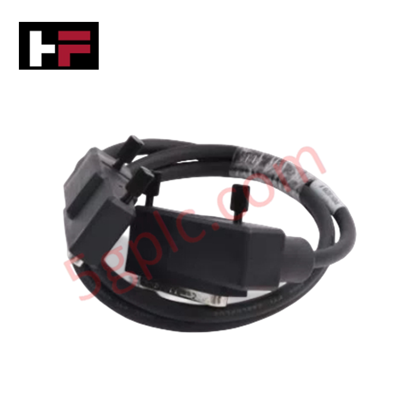
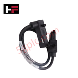
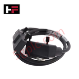
The Foxboro P0931RQ, also cataloged as the P0931RQ Cordset Cable, operates as a dedicated hardware component for high-speed data transfer and Fieldbus Module interconnectivity within Foxboro I/A Series control networks. It routes digital signals between DIN FBM devices and system backplane interfaces via a 24 AWG shielded conductor path.
Hardware Specifications
| Parameter | Specification |
|---|---|
| Model | P0931RQ |
| Brand | Foxboro |
| Origin | USA |
| Weight | Approx. 0.35 lbs |
| Dimensions | Cable length 2 meters |
| Operating Temp | -40 deg C to +85 deg C |
| Power Consumption | Passive physical conductor path |
| Voltage Rating | 300 V |
| Data Rate | Up to 1 Gbps |
| Conductor Size | 24 AWG |
| Jacket Material | Polyurethane |
| Shielding Type | Foil and braid double shielding |
| Connector Type | DIN FBM |
Fieldbus Transmission Integrity and Channel Isolation
The Foxboro P0931RQ utilizes dual-layer foil and braid shielding to prevent electromagnetic interference from degrading high-speed serial data signals transmitted up to 1 Gbps. By maintaining continuous ground shield continuity across DIN FBM interconnect points, the assembly provides channel-to-channel isolation and suppresses ground loop transients. This configuration protects low-level 4-20 mA HART analog digital pass-through signals from adjacent high-voltage power lines.
Frequently Asked Questions
Q: What is the minimum bend radius required during cable routing?
A: To prevent damage to the inner 24 AWG conductors and preserve shield braid density, maintain a minimum dynamic bend radius of at least 10 times the outer cable diameter during installation.
Q: Can the P0931RQ cordset be connected or disconnected while system backplanes are powered?
A: Hot-swapping the DIN FBM connector is permitted if the associated I/O rack hardware supports live insertion. However, care must be taken to ensure the metallic shield collar contacts the chassis ground ring first to discharge static potentials.
Field Installation Guidelines
Route the polyurethane-jacketed cable through dedicated low-voltage instrument trays, keeping a minimum clearance of 300 mm from 480 VAC or higher AC power conduits to minimize noise coupling.
Ensure the DIN FBM connectors are fully seated into the mating module receptacles until locking latches engage completely. Terminate the overall foil and braid shield drain wire to the cabinet single-point ground bar. When passing through enclosure walls, utilize appropriate cable glands and maintain a minimum 5-thread engagement for NPT conduit entries to ensure IP-rated environmental sealing.
Additional Information
- 100% Genuine Parts: All products are original and authentic, ensuring reliable industrial performance.
- 30-Day Refund Guarantee: Return any in-stock item within 30 days in original, unopened packaging for a full refund (excluding shipping and fees).
- 12-Month Warranty: Covers defects in materials or workmanship; excludes misuse, normal wear, or unauthorized modifications.
- Worldwide Shipping: We ship via USPS, UPS, FedEx, and DHL. Delivery times vary by country and may be subject to customs or import fees.
- Support & Contact: Technical and warranty assistance is available anytime. Contact us here: Contact.
- Purchase Guidance: Check product specifications and compatibility carefully before ordering to ensure proper application.






Tech & Buying Guide

Redefining Control Systems: The Rise of Flexible I/O Modules in Industrial Automation
Conventional input-output architectures often limit engineering agility and inflate long-term inventory costs. Today, Flexible Input/Output Modules (FIOM) are transforming how control system engineers design, commission, and maintain automation infrastructure. By allowing individual channel software configuration, FIOM technology bridges the gap between rigid hardware design and dynamic plant requirements.

Understanding Modern SCADA Systems: Architecture, Communication Topologies, and Industrial Applications
Supervisory Control and Data Acquisition (SCADA) systems form the digital backbone of modern industrial automation. They collect critical field data, transmit signals across vast distances, and empower plant operators with real-time process visibility. Across modern infrastructures, SCADA solutions streamline centralized control and maintain continuous operational uptime.

Understanding OPC Servers in Modern Industrial Automation: Principles, Architecture, and Applications
In industrial automation, connecting physical hardware with high-level software remains a primary operational challenge. Factories utilize programmable logic controllers (PLCs), distributed control systems (DCS), human-machine interfaces (HMIs), and smart sensors from diverse vendors. These devices often speak different proprietary protocols. Open Platform Communications (OPC) servers solve this interoperability challenge by standardizing how data flows across factory networks.