


Product Details
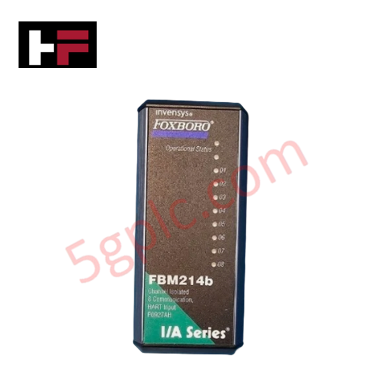
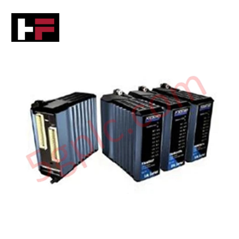
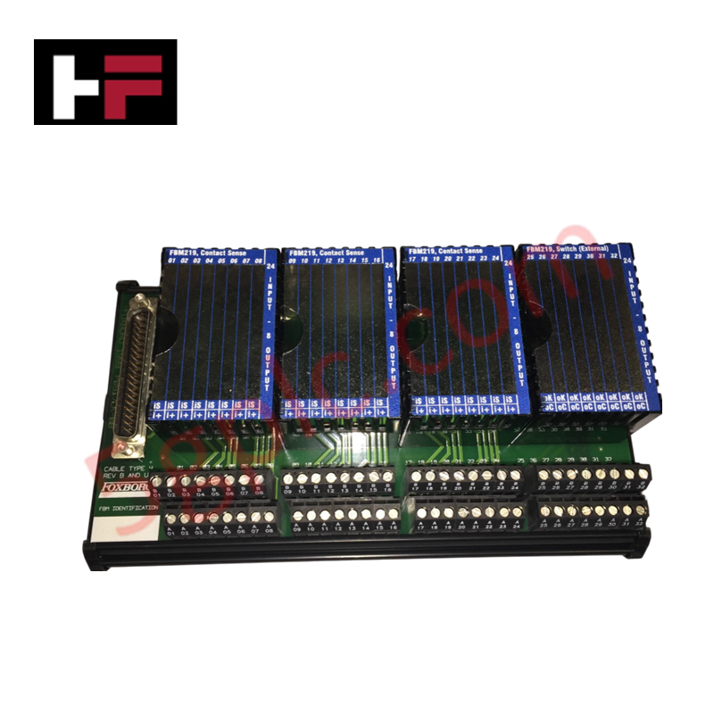
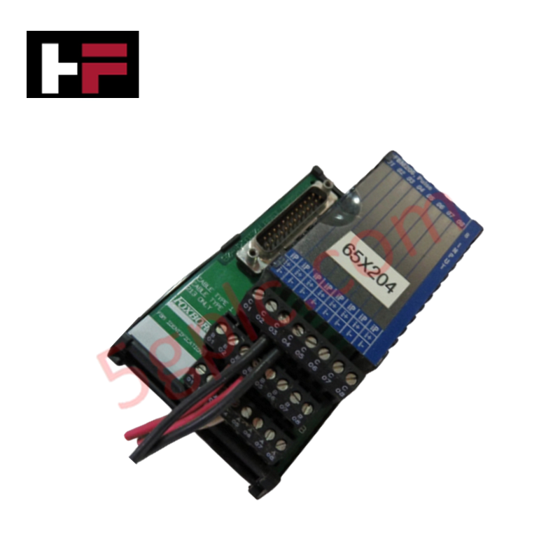
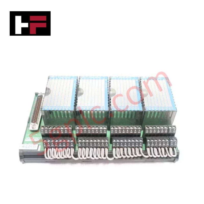
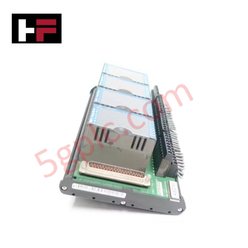
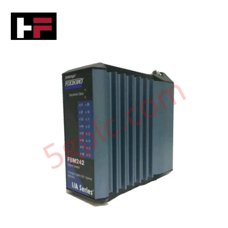
Configured for signal acquisition in I/A Series control networks, the Foxboro Invensys FBM214B RH927AH (FBM214B Input Module) provides direct physical/electrical execution. This hardware component serves as the primary interface for 8 analog input channels, facilitating the transmission of 4-20 mA signals and superimposed HART digital FSK data from field instrumentation to the control platform.
Hardware Specifications
| Parameter | Specification |
|---|---|
| Model | FBM214B RH927AH |
| Brand | Foxboro (Schneider Electric) |
| Origin | Manufacturer Standard |
| Weight | 0.3 kg |
| Dimensions | 2.2 cm x 12.4 cm x 12.6 cm |
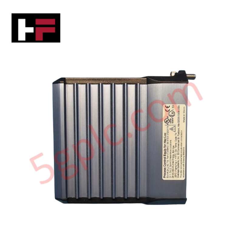
| Operating Temp | -20 deg C to 60 deg C |
| Power Consumption | Passive (Loop powered) |
| Channel Count | 8 Analog Input Channels |
| Input Resistance | 280 Ohm nominal |
| Resolution | 15 bits |
DCS Process Instrumentation Connectivity
The FBM214B maintains process signal fidelity through robust channel-to-channel isolation, minimizing noise coupling in high-density I/O arrays. The module supports 4-20 mA HART loop protocol connectivity, allowing for real-time digital diagnostics and asset management of field devices. With a common-mode rejection ratio exceeding 100 dB at 50/60 Hz, the hardware effectively suppresses induced electromagnetic interference common in industrial installations. Cold junction compensation (CJC) and precise resistance scaling are implemented to ensure loop accuracy within 0.03% of full scale.
Frequently Asked Questions
Q: Can the FBM214B be hot-swapped while the field loop is active?
A: The module is designed for replacement in I/A Series modular baseplates; however, maintain system-level safety protocols when extracting the module to avoid inadvertent interruption of the field loop continuity.
Q: How does the module handle superimposed HART digital messages?
A: The FBM214B utilizes dedicated internal circuitry to demodulate FSK signals superimposed on the 4-20 mA DC current, providing the host controller with both primary process variables and secondary digital diagnostic data simultaneously.
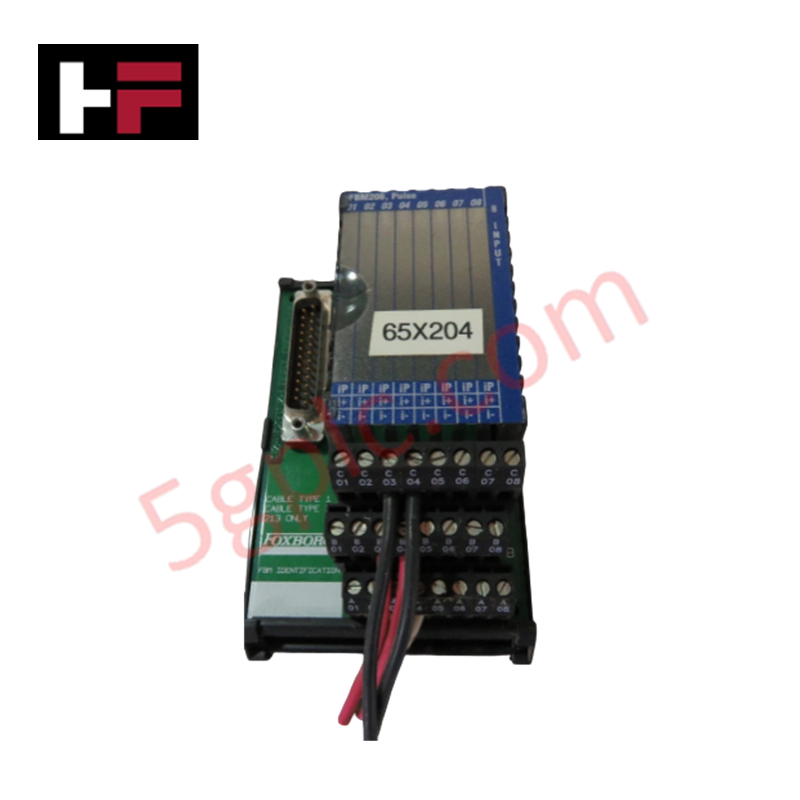
Field Installation Guidelines
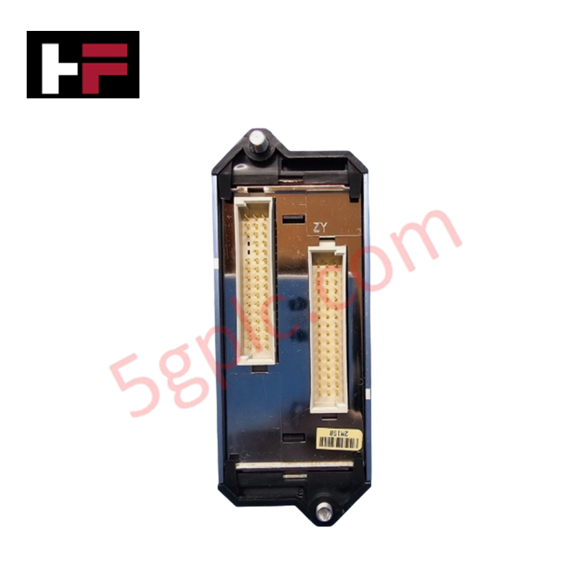
- Mount the module onto the corresponding termination assembly, ensuring the backplane connector is correctly aligned to prevent pin damage.
- Verify that field wiring is shielded and that drain wires are terminated at the designated cabinet grounding bus to ensure electromagnetic compatibility.
- Observe the 100 ms per channel update rate during control loop tuning to ensure timing requirements for high-speed process responses are met.
- Ensure the sense resistor loading (61.5 Ohm) is accounted for when calculating total loop resistance and power supply voltage drop requirements.
- Inspect LED status indicators post-installation to confirm the module is communicating correctly with the Fieldbus communication processor.
Additional Information
- 100% Genuine Parts: All products are original and authentic, ensuring reliable industrial performance.
- 30-Day Refund Guarantee: Return any in-stock item within 30 days in original, unopened packaging for a full refund (excluding shipping and fees).
- 12-Month Warranty: Covers defects in materials or workmanship; excludes misuse, normal wear, or unauthorized modifications.
- Worldwide Shipping: We ship via USPS, UPS, FedEx, and DHL. Delivery times vary by country and may be subject to customs or import fees.
- Support & Contact: Technical and warranty assistance is available anytime. Contact us here: Contact.
- Purchase Guidance: Check product specifications and compatibility carefully before ordering to ensure proper application.


Tech & Buying Guide

Strategic Selection: Choosing the Right SCADA Software for Your PLC Project
In industrial automation, the SCADA (Supervisory Control and Data Acquisition) system acts as the bridge between raw machine data and actionable human intelligence. Selecting the incorrect software platform can lead to integration bottlenecks, scalability issues, and excessive long-term maintenance costs. As an automation consultant with 15 years of experience, I have guided many projects through the selection process. Below are the essential criteria for choosing a platform that ensures both performance and longevity.

Ensuring Operational Continuity: The Strategic Value of Redundant Automation Systems
In modern industrial landscapes, unplanned downtime is the ultimate adversary. For sectors relying on complex PLC and DCS architectures, a single hardware failure can trigger catastrophic production losses. Therefore, implementing redundant automation systems is no longer a luxury; it is a fundamental requirement for mission-critical operations. In this article, I analyze why redundancy remains the backbone of reliable industrial infrastructure.

Selecting the Right Cables for Industrial Automation: A Comprehensive Guide
Selecting the appropriate cabling infrastructure is critical for the success of any industrial automation project. Improper cable selection often leads to signal degradation, system instability, and costly downtime. As an automation engineer, I frequently see projects compromised by poor cabling choices in harsh industrial environments. This guide simplifies the complex landscape of cabling to help you make informed decisions for your PLC, DCS, and control systems.