


Product Details
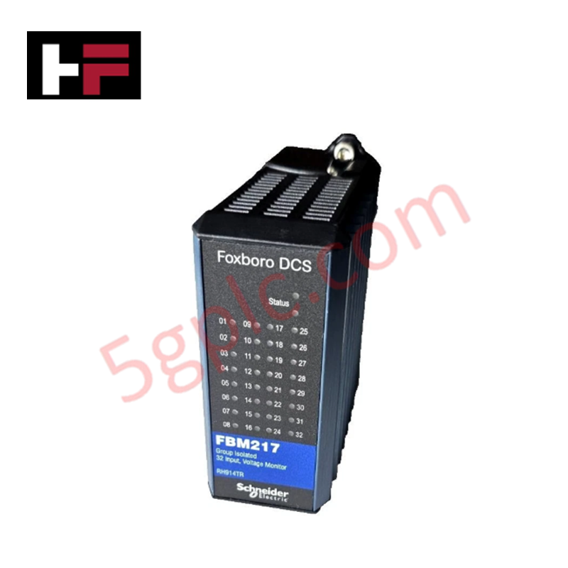
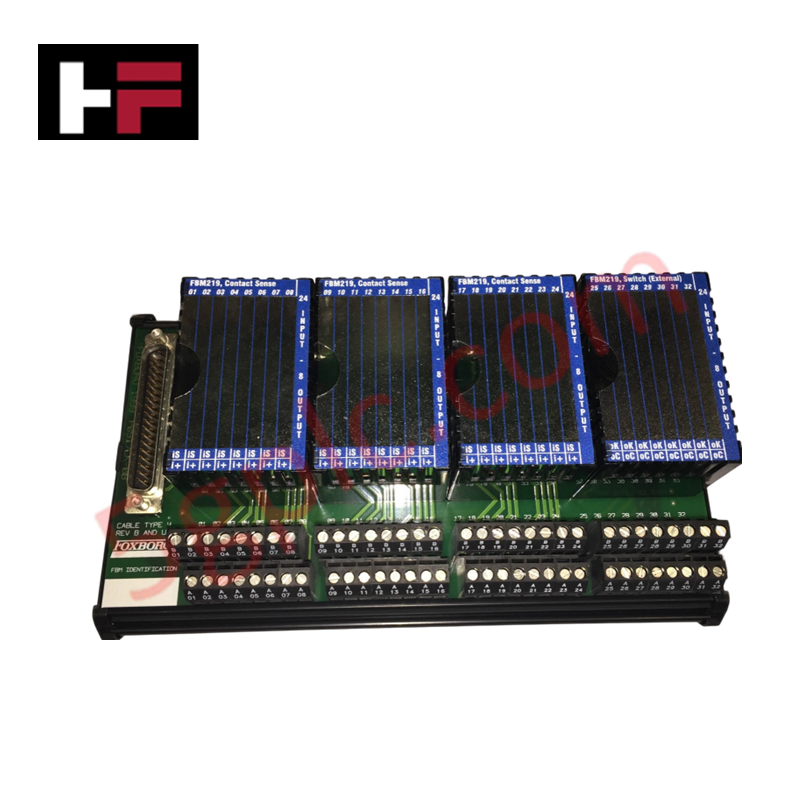
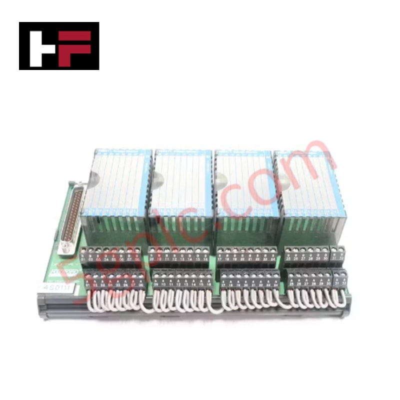
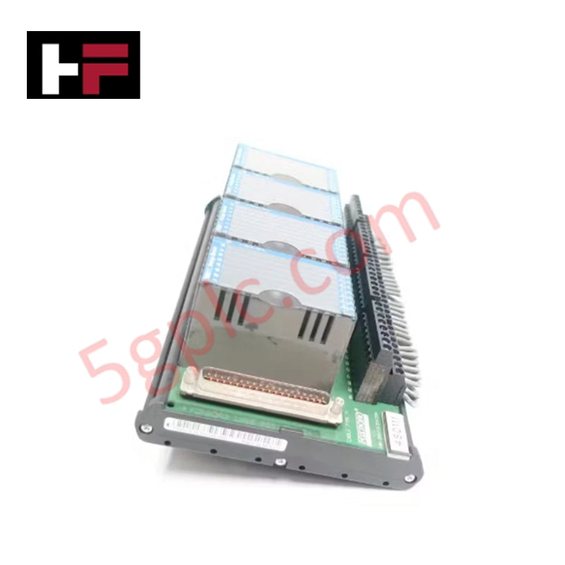
Configured for high-density signal acquisition in I/A Series control networks, the Foxboro FBM217 RH914TR (FBM217 Discrete Input Module) provides direct physical/electrical execution. This hardware component serves as the primary interface for 32 discrete input channels, facilitating the conversion of multi-voltage field signals into digital data for processing across I/A Series platforms.
Suffix Breakdown & Model Matrix
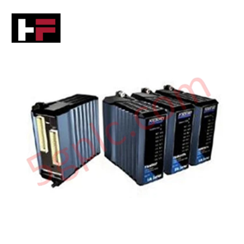
The RH914TR designation corresponds to the base FBM217 hardware configuration designed for standard discrete input density. No additional variants exist for this specific base model architecture; the unit is natively designed for both single and redundant module pair deployment.
Hardware Specifications
| Parameter | Specification |
|---|---|
| Model | FBM217 RH914TR |
| Brand | Foxboro |
| Origin | Manufacturer Standard |
| Weight | Not specified |
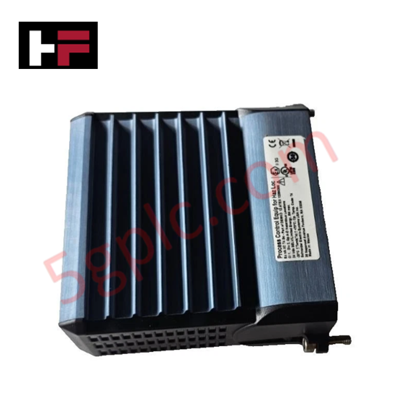
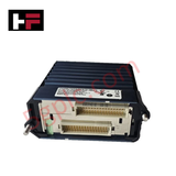
| Dimensions | Standard I/A Series module form factor |
| Operating Temp | -20 deg C to 60 deg C |
| Power Consumption | 3 W at 24 VDC |
| Channel Count | 32 discrete input channels |
| Supported Voltages | 15-60 VDC, 120 VAC/125 VDC, 240 VAC |
| Communication | 2 Mbps module Fieldbus |
Industrial Control System Connectivity
The FBM217 module supports high-density I/O density scaling within DCS architectures, allowing for efficient space utilization in control cabinets. Integration with deterministic networks ensures that input state transitions are captured with minimal latency. Firmware flash compatibility is managed via the module's communication interface, permitting site-wide updates to debounce logic and filter settings through the FCM or FCP controller. The module's internal logic handles debouncing configurations of 0, 4, 8, 16, or 32 ms to suppress contact bounce in mechanical field switches.
Frequently Asked Questions
Q: Does the FBM217 support redundant module configurations?
A: Yes, the FBM217 supports both single and redundant configurations. When deployed in a redundant pair, the module handles synchronized state monitoring to maintain process continuity during a primary module fault.
Q: How is the input filtering/debounce configured?
A: The debounce period is software-configurable via the control system interface. Available settings include 0 ms (no filtering), 4 ms, 8 ms, 16 ms, or 32 ms, which must be selected based on the mechanical characteristics of the connected field device.
Field Installation Guidelines
- Ensure the mounting base (Termination Assembly) is securely fixed to the DIN rail or rack prior to module insertion.
- Verify that the system bus power is within the specified 24 VDC +5%, -10% range before seating the module to avoid damage to the communication transceiver.
- Terminate field signal wiring to the corresponding terminal assembly blocks, ensuring the off-state source resistance meets the 100 kOhm minimum requirement to prevent false high states.
- If using a redundant configuration, ensure both FBM217 modules are properly seated and communicating with the redundant controller pair.
- Inspect the backplane connectors for proper alignment and pin integrity; verify the 2 Mbps Fieldbus link is active via the module status LED indicators upon power-up.
Additional Information
- 100% Genuine Parts: All products are original and authentic, ensuring reliable industrial performance.
- 30-Day Refund Guarantee: Return any in-stock item within 30 days in original, unopened packaging for a full refund (excluding shipping and fees).
- 12-Month Warranty: Covers defects in materials or workmanship; excludes misuse, normal wear, or unauthorized modifications.
- Worldwide Shipping: We ship via USPS, UPS, FedEx, and DHL. Delivery times vary by country and may be subject to customs or import fees.
- Support & Contact: Technical and warranty assistance is available anytime. Contact us here: Contact.
- Purchase Guidance: Check product specifications and compatibility carefully before ordering to ensure proper application.


Tech & Buying Guide

Strategic Selection: Choosing the Right SCADA Software for Your PLC Project
In industrial automation, the SCADA (Supervisory Control and Data Acquisition) system acts as the bridge between raw machine data and actionable human intelligence. Selecting the incorrect software platform can lead to integration bottlenecks, scalability issues, and excessive long-term maintenance costs. As an automation consultant with 15 years of experience, I have guided many projects through the selection process. Below are the essential criteria for choosing a platform that ensures both performance and longevity.

Ensuring Operational Continuity: The Strategic Value of Redundant Automation Systems
In modern industrial landscapes, unplanned downtime is the ultimate adversary. For sectors relying on complex PLC and DCS architectures, a single hardware failure can trigger catastrophic production losses. Therefore, implementing redundant automation systems is no longer a luxury; it is a fundamental requirement for mission-critical operations. In this article, I analyze why redundancy remains the backbone of reliable industrial infrastructure.

Selecting the Right Cables for Industrial Automation: A Comprehensive Guide
Selecting the appropriate cabling infrastructure is critical for the success of any industrial automation project. Improper cable selection often leads to signal degradation, system instability, and costly downtime. As an automation engineer, I frequently see projects compromised by poor cabling choices in harsh industrial environments. This guide simplifies the complex landscape of cabling to help you make informed decisions for your PLC, DCS, and control systems.