












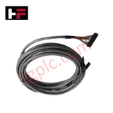

Product Details
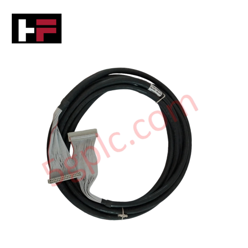
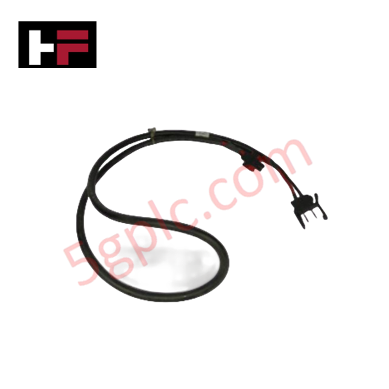
The Honeywell FC-SICC-0001/L10, also cataloged as the FC-SICC-0001 Interconnection Cable, operates as a dedicated hardware component for high-integrity optical signal transmission and subsystem communication within Honeywell Safety Manager platforms.
Hardware Specifications
| Parameter | Specification |
|---|---|
| Model | FC-SICC-0001/L10 |
| Brand | Honeywell |
| Origin | USA |
| Weight | 0.38 kg |
| Dimensions | 12.0 cm x 19.0 cm x 2.0 cm |
| Operating Temp | -20 to +60 deg C |
| Power Consumption | Passive optical media (Zero internal power draw) |
| Cable Type | Dual-channel fiber-optic assembly |
| Cable Length | 10 m (indicated by /L10 suffix) |
| Interface Type | Redundant optical connectors |
| Safety Rating | SIL3 compliant (IEC 61508 / IEC 61511) |
| System Compatibility | Honeywell Safety Manager, Experion PKS, C300 controllers |
Process Control & DCS Optical Communication Characteristics
The FC-SICC-0001/L10 interconnection cable provides complete galvanic isolation between controller racks, eliminating ground loop current flows and high-frequency noise coupling across system nodes. Designed for SIL3 safety instrumented loops, the dual-channel fiber architecture transports redundant telemetry without signal degradation or cross-talk. The non-conductive dielectric construction prevents signal interference when routed parallel to 4-20 mA HART loop protocol field wiring or high-power distribution buses.
Frequently Asked Questions
Q: How does the FC-SICC-0001/L10 handle channel maintenance during live controller operation?
A: Optical signal transmission permits live hot-swapping or physical disconnection of an individual channel without generating electrical switching transients or interrupting the secondary redundant optical link on active Safety Manager networks.
Q: What precautions should be taken regarding optical connector hygiene prior to installation?
A: Keep protective dust boots in place until the moment of connection. Always clean the optical ferrule faces with lint-free wipes and isopropyl alcohol to prevent insertion loss caused by dust accumulation.
Field Installation Guidelines
- Bending Radius Limitations: Maintain a minimum static bending radius of 30 mm during cabinet installation to avoid micro-bending optical attenuation or internal fiber fracture.
- Connector Insertion: Align optical connectors carefully with module ports until the locking mechanism clicks firmly into position. Avoid applying excessive tensile force to the cable lead.
- Tray Routing & Segregation: Secure the fiber assembly using soft velcro ties along dedicated low-voltage instrument trays. Avoid physical crushing forces from heavy copper cable bundles.
- Redundant Path Physical Separation: Route primary and secondary fiber branches through separate cabinet entry points or ductways to preserve system availability against localized physical damage.
Additional Information
- 100% Genuine Parts: All products are original and authentic, ensuring reliable industrial performance.
- 30-Day Refund Guarantee: Return any in-stock item within 30 days in original, unopened packaging for a full refund (excluding shipping and fees).
- 12-Month Warranty: Covers defects in materials or workmanship; excludes misuse, normal wear, or unauthorized modifications.
- Worldwide Shipping: We ship via USPS, UPS, FedEx, and DHL. Delivery times vary by country and may be subject to customs or import fees.
- Support & Contact: Technical and warranty assistance is available anytime. Contact us here: Contact.
- Purchase Guidance: Check product specifications and compatibility carefully before ordering to ensure proper application.


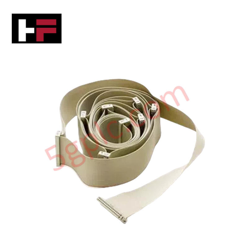
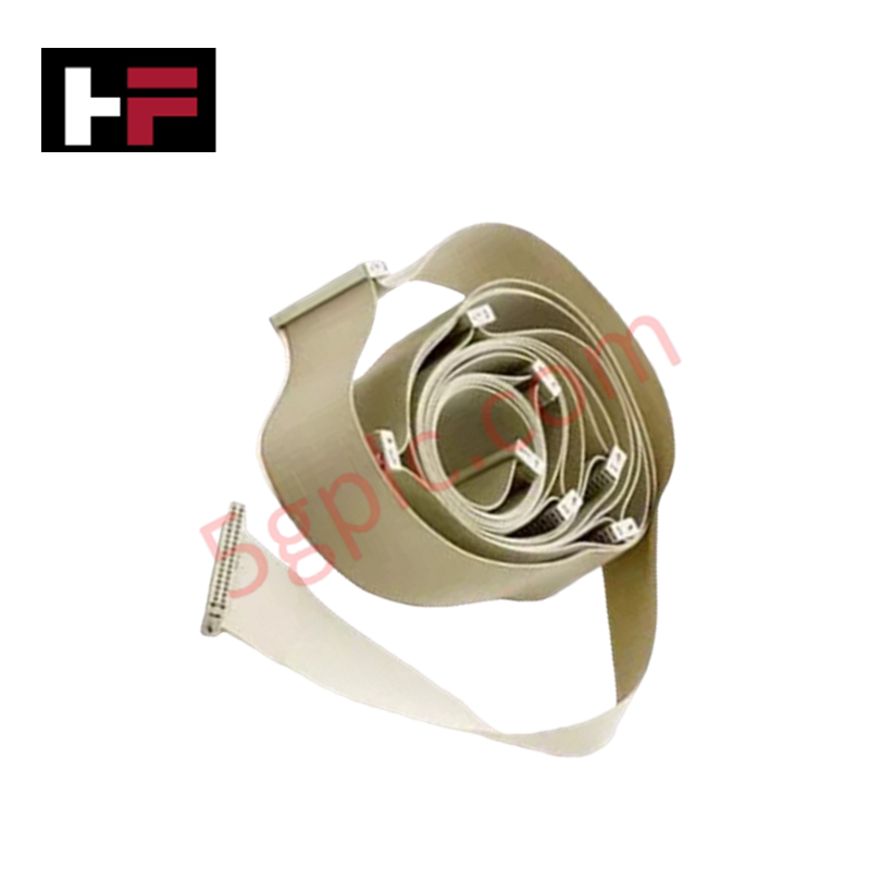


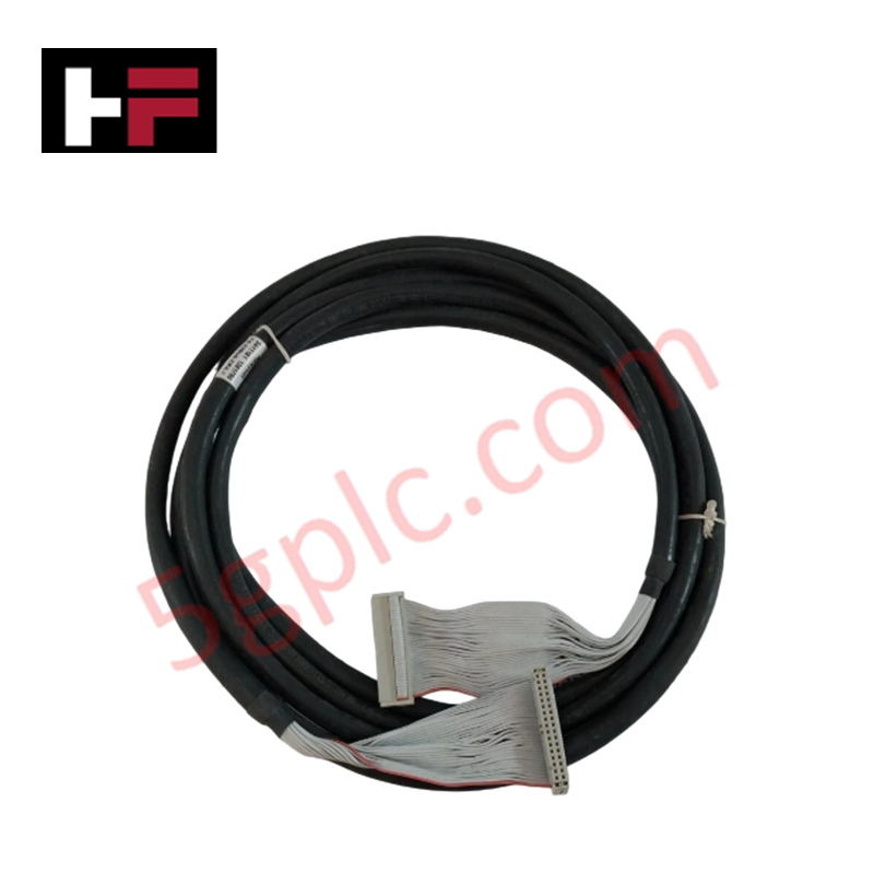



Tech & Buying Guide
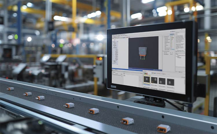
Modern Industrial Automation: Transforming Safety and Efficiency in Mining Operations
Industrial automation has evolved from a simple manufacturing tool into the operational backbone of high-risk sectors. Modern mining operations increasingly rely on advanced control systems, programmable logic controllers (PLCs), distributed control systems (DCS), and artificial intelligence to address deep-underground hazards. By replacing manual labor in high-risk zones, factory automation technologies protect personnel while significantly boosting operational throughput.

Step-by-Step System Cabinet Health Check Guide for PLC and DCS Infrastructure
