












Product Details
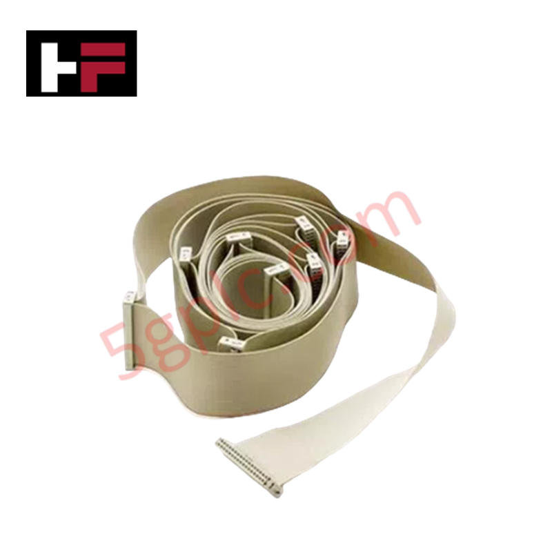
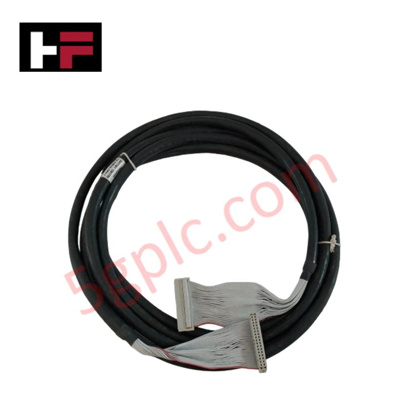
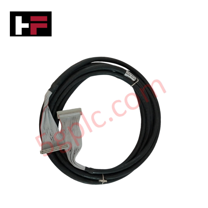
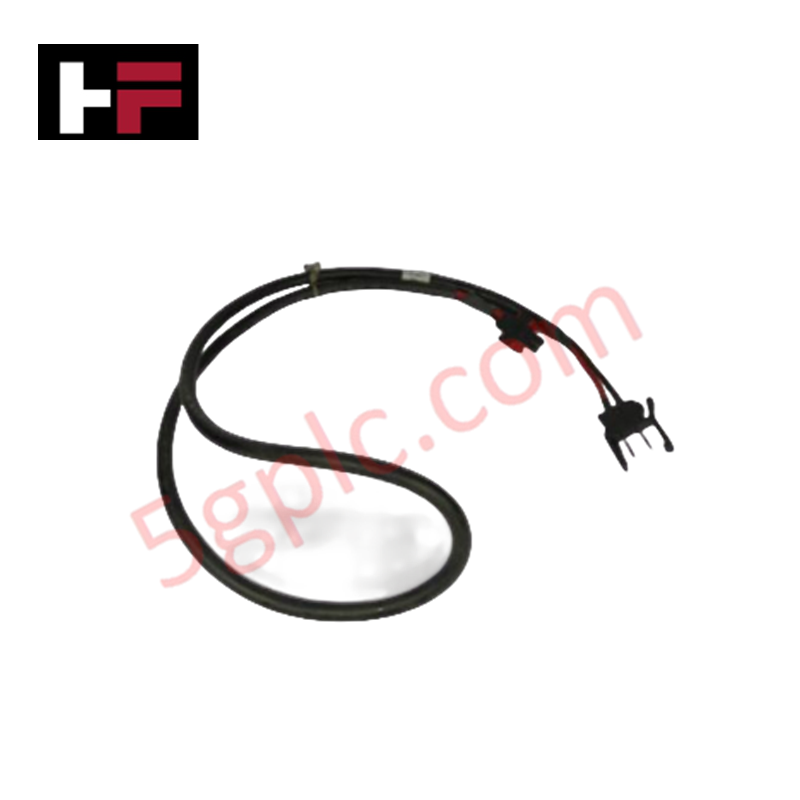
Configured for high-integrity inter-rack signal routing in Honeywell safety platforms, the Honeywell FS-SICC-0001/L3 (FS-SICC-0001 System Interconnection Cable) provides direct physical/electrical execution. It links processing chassis to remote I/O sub-assemblies across a 3 m double-shielded cable assembly.
Hardware Specifications
| Parameter | Specification |
|---|---|
| Model | FS-SICC-0001/L3 |
| Brand | Honeywell |
| Origin | USA |
| Weight | 2.0 kg (shipping weight) |
| Dimensions | Outer diameter 9.93 mm (0.39 in) x 3 m length |
| Operating Temp | -20 to +60 deg C |
| Power Consumption | Passive interconnect assembly (Zero internal power draw) |
| Cable Structure | 20 x AWG 22 (0.34 mm2) conductors |
| Shielding | Double-shielded construction |
| Cable Type | System Interconnection Cable For Chassis IO |
| System Compatibility | Honeywell Safety Manager / FSC platforms |
Process Control & DCS Signal Interconnection Characteristics
, The FS-SICC-0001/L3 cable features channel-to-channel isolation principles to suppress electromagnetic interference during transmission between control chassis and field termination interfaces. The 20-conductor double-shielded copper architecture limits noise coupling and signal degradation across the 3 m distance, providing deterministic pass-through for discrete logic signals and 4-20 mA HART loop protocol field telemetry.
Frequently Asked Questions
Q: What impact does the double-shielded construction have on noise rejection in high-EMI environments?
A: The dual foil and braid shielding isolates the internal 20 AWG 22 conductors from stray capacitive and inductive interference, preserving signal fidelity across chassis interconnections.
Q: Can the FS-SICC-0001/L3 cable be disconnected while the system chassis is under power?
A: Disconnection during active operation is permissible only in redundant I/O rack configurations; removing an active single-channel cable will disconnect live process I/O channels from the central controller logic.
Field Installation Guidelines
- Routing and Bend Radius: Layout the 3 m cable within low-voltage wire raceways or cable trays. Ensure the static bend radius remains above 60 mm to prevent conductor fatigue and shield tearing.
- Connector Alignment: Align connector orientation keys precisely with the target chassis I/O interface. Fully seat the connector housing and tighten retaining hardware to resist vibration.
- Shield Grounding: Crimp and connect the shield drain wire to the central cabinet earth grounding point to avoid ground potential loops between connected chassis.
- Raceway Separation: Maintain at least 30 cm clearance between the system interconnection cable and high-voltage AC distribution or motor power cabling.
Additional Information
- 100% Genuine Parts: All products are original and authentic, ensuring reliable industrial performance.
- 30-Day Refund Guarantee: Return any in-stock item within 30 days in original, unopened packaging for a full refund (excluding shipping and fees).
- 12-Month Warranty: Covers defects in materials or workmanship; excludes misuse, normal wear, or unauthorized modifications.
- Worldwide Shipping: We ship via USPS, UPS, FedEx, and DHL. Delivery times vary by country and may be subject to customs or import fees.
- Support & Contact: Technical and warranty assistance is available anytime. Contact us here: Contact.
- Purchase Guidance: Check product specifications and compatibility carefully before ordering to ensure proper application.






Tech & Buying Guide

Modern Industrial Automation: Transforming Safety and Efficiency in Mining Operations
Industrial automation has evolved from a simple manufacturing tool into the operational backbone of high-risk sectors. Modern mining operations increasingly rely on advanced control systems, programmable logic controllers (PLCs), distributed control systems (DCS), and artificial intelligence to address deep-underground hazards. By replacing manual labor in high-risk zones, factory automation technologies protect personnel while significantly boosting operational throughput.

Step-by-Step System Cabinet Health Check Guide for PLC and DCS Infrastructure
