


Product Details
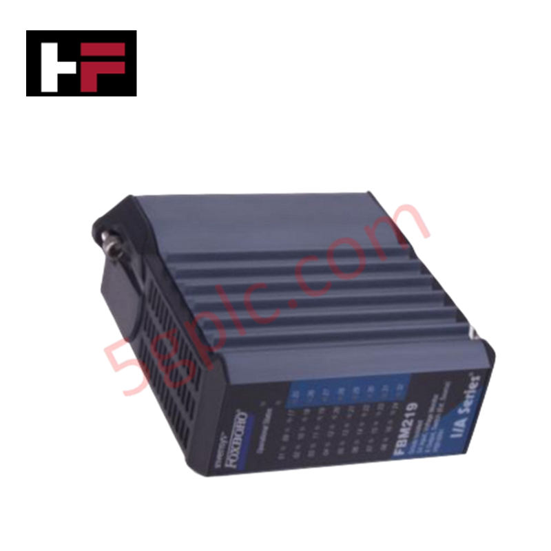
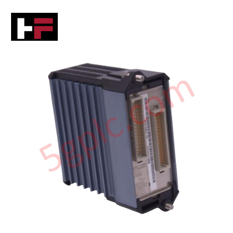
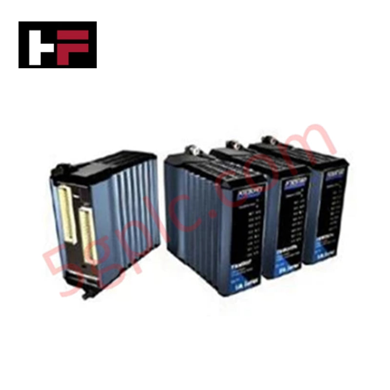
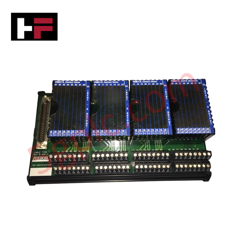
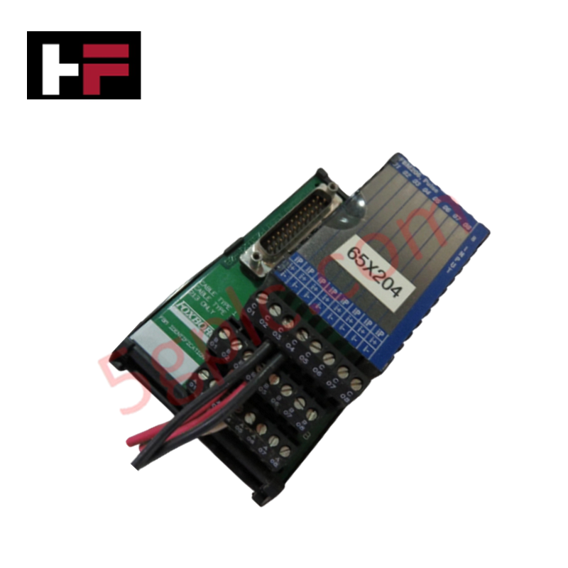
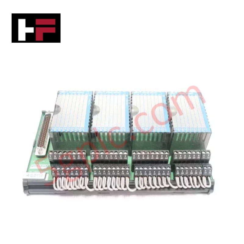
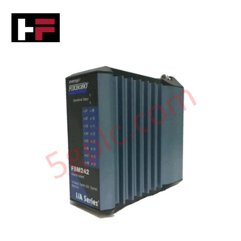
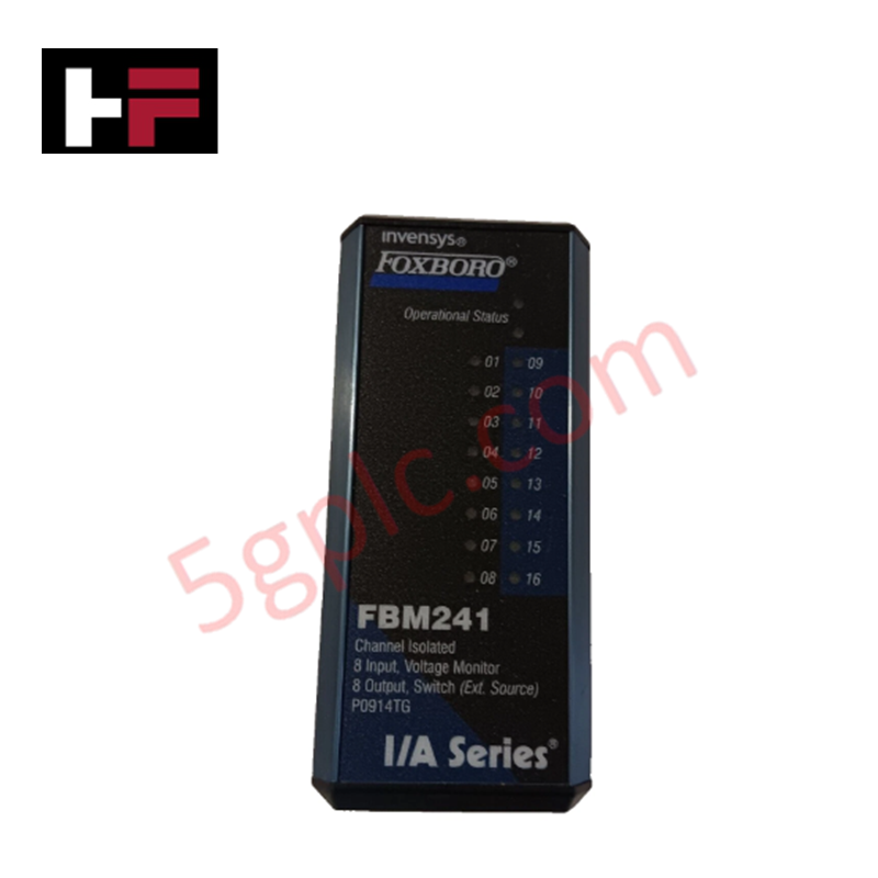
Configured for discrete voltage monitoring and signal switching in I/A Series DCS platforms, the Foxboro FBM219 P0916RH (FBM219 Voltage Monitor Module) provides direct physical execution of 24-input monitoring and 8-output control.
Hardware Specifications
| Parameter | Specification |
|---|---|
| Model | FBM219 P0916RH |
| Brand | Foxboro |
| Origin | United States |
| Weight | 0.3 kg |
| Dimensions | 10.5 cm x 10 cm x 4 cm |
| Operating Temp | Not specified |
| Power Consumption | Not specified |
| I/O Capacity | 24 inputs / 8 outputs |
| Fusing | 0.25 A integrated fuse |
4-20 mA HART Loop Protocol
The FBM219 module interfaces with field loops to monitor voltage levels and execute discrete output commands. While the primary function involves discrete state monitoring rather than analog loop control, the module maintains channel-to-channel isolation to prevent potential cross-talk between input and output circuits. Integration with HART-capable field instruments is supported through the DCS backplane, where the FBM219 provides the necessary voltage status feedback to the I/A Series host. Proper implementation of HART communication requires that the module and associated field devices are configured to ensure that signal frequency components are not suppressed by the module's input filtering characteristics.
Frequently Asked Questions
Q: Does the FBM219 support hot-swapping under normal operating conditions?
A: Yes, the module supports hot-swapping within the I/A Series baseplate environment. Users must ensure that the associated I/O channels are placed in a safe state via the control software to prevent unintended output activation or state changes during module insertion or removal.
Q: How is the integrated 0.25 A fuse managed in the event of an output overcurrent?
A: The 0.25 A fuse provides overcurrent protection for the output circuits. If a fault causes the fuse to open, the module must be removed, and the fuse condition verified. Fuses are typically non-serviceable by the end-user; refer to factory maintenance protocols for module replacement.
Field Installation Guidelines
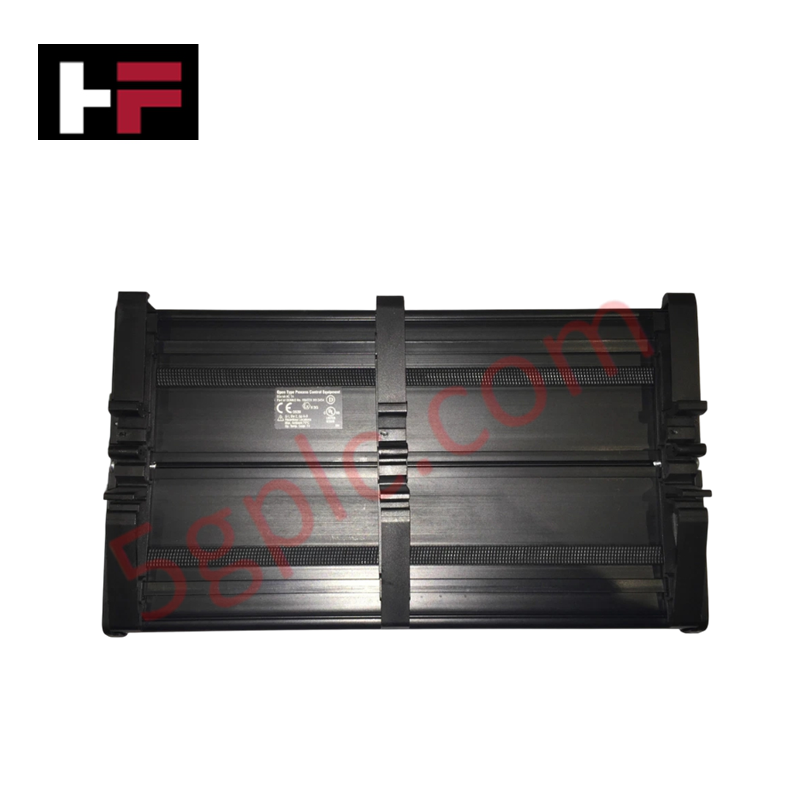
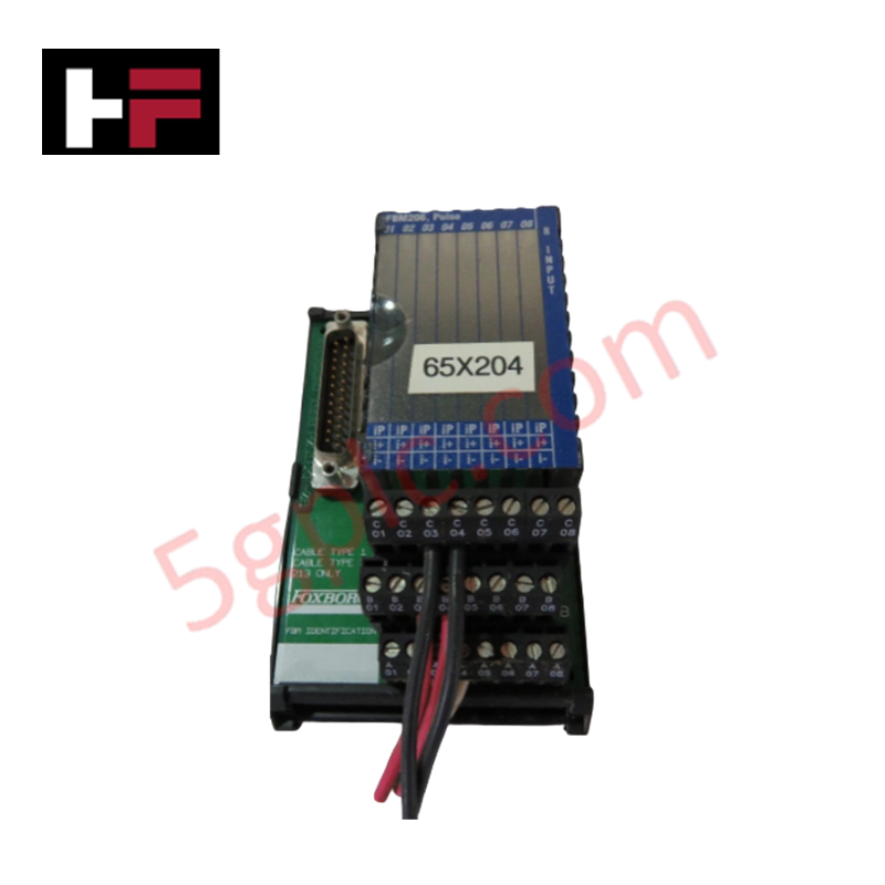
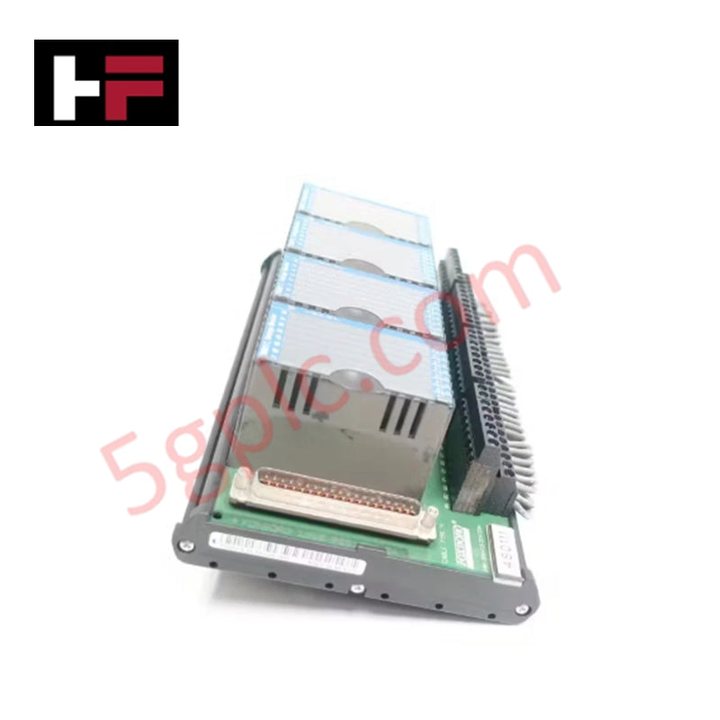
- Mount the module onto the dedicated Modular Baseplate, ensuring the mechanical connectors are fully seated to establish the backplane bus communication link.
- Terminate all input and output wiring at the termination assembly (TA), observing the voltage limits of 60 V for monitoring inputs.
- Verify that the shield drain wires are terminated to the chassis ground at the cabinet entry point to reduce common-mode noise on the voltage monitor inputs.
- Confirm that the module orientation allows for adequate thermal dissipation, as the internal switching circuitry generates heat under full load conditions.
- Perform a point-to-point I/O check using the I/A Series configuration software to confirm that each of the 24 inputs and 8 outputs responds correctly to field-side stimuli before commissioning the control loop.
Additional Information
- 100% Genuine Parts: All products are original and authentic, ensuring reliable industrial performance.
- 30-Day Refund Guarantee: Return any in-stock item within 30 days in original, unopened packaging for a full refund (excluding shipping and fees).
- 12-Month Warranty: Covers defects in materials or workmanship; excludes misuse, normal wear, or unauthorized modifications.
- Worldwide Shipping: We ship via USPS, UPS, FedEx, and DHL. Delivery times vary by country and may be subject to customs or import fees.
- Support & Contact: Technical and warranty assistance is available anytime. Contact us here: Contact.
- Purchase Guidance: Check product specifications and compatibility carefully before ordering to ensure proper application.


Tech & Buying Guide

Strategic Selection: Choosing the Right SCADA Software for Your PLC Project
In industrial automation, the SCADA (Supervisory Control and Data Acquisition) system acts as the bridge between raw machine data and actionable human intelligence. Selecting the incorrect software platform can lead to integration bottlenecks, scalability issues, and excessive long-term maintenance costs. As an automation consultant with 15 years of experience, I have guided many projects through the selection process. Below are the essential criteria for choosing a platform that ensures both performance and longevity.

Ensuring Operational Continuity: The Strategic Value of Redundant Automation Systems
In modern industrial landscapes, unplanned downtime is the ultimate adversary. For sectors relying on complex PLC and DCS architectures, a single hardware failure can trigger catastrophic production losses. Therefore, implementing redundant automation systems is no longer a luxury; it is a fundamental requirement for mission-critical operations. In this article, I analyze why redundancy remains the backbone of reliable industrial infrastructure.

Selecting the Right Cables for Industrial Automation: A Comprehensive Guide
Selecting the appropriate cabling infrastructure is critical for the success of any industrial automation project. Improper cable selection often leads to signal degradation, system instability, and costly downtime. As an automation engineer, I frequently see projects compromised by poor cabling choices in harsh industrial environments. This guide simplifies the complex landscape of cabling to help you make informed decisions for your PLC, DCS, and control systems.