Product Details
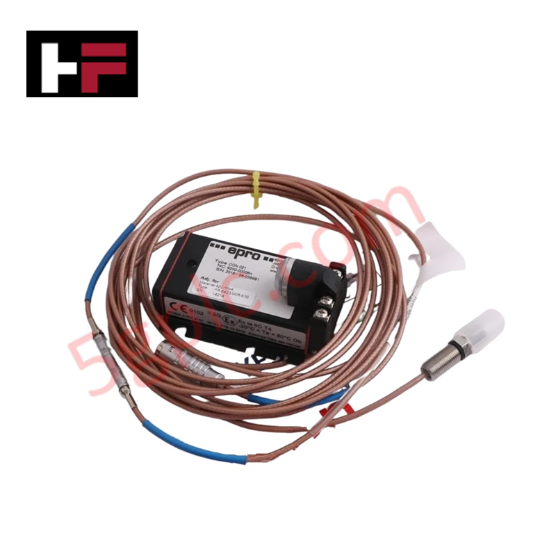
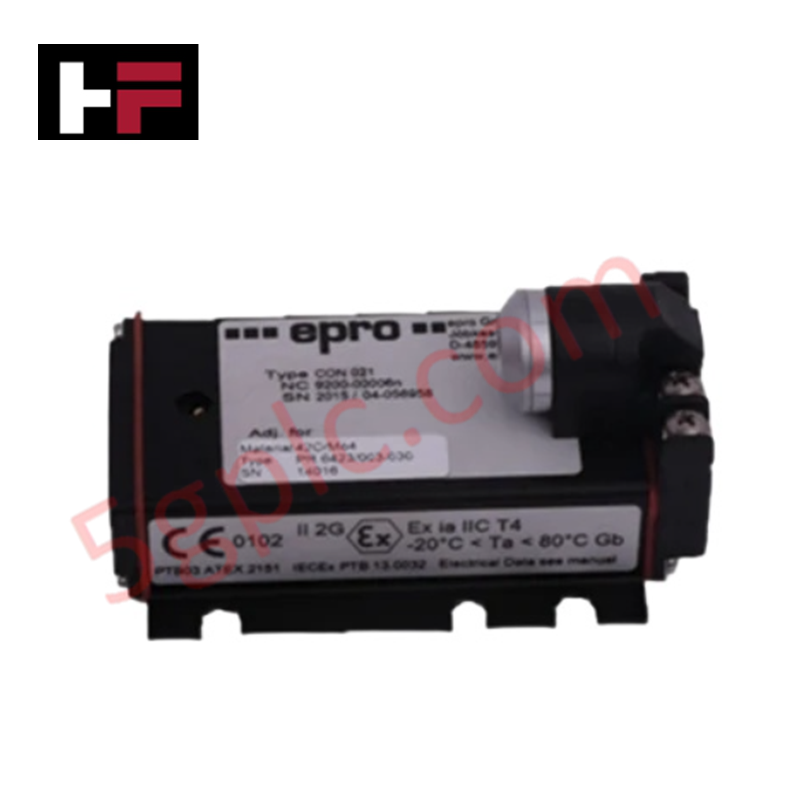
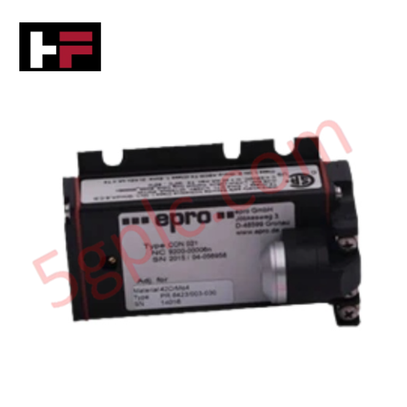
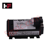
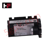
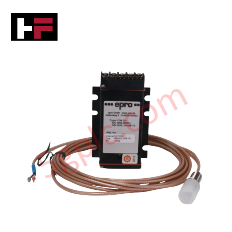
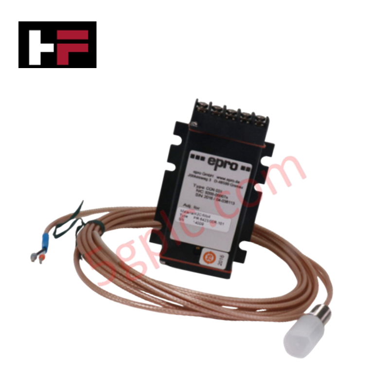
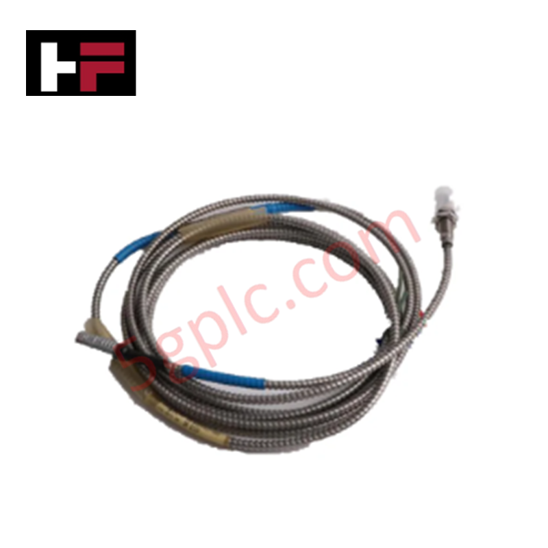
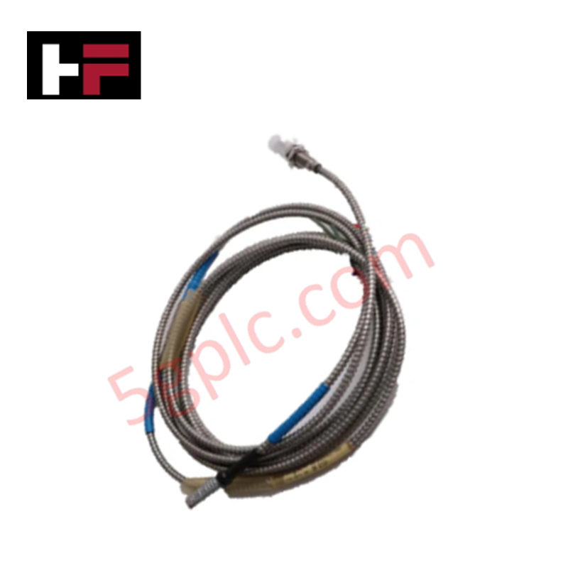
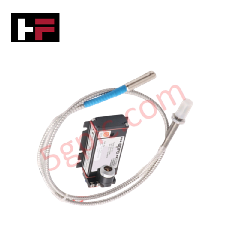
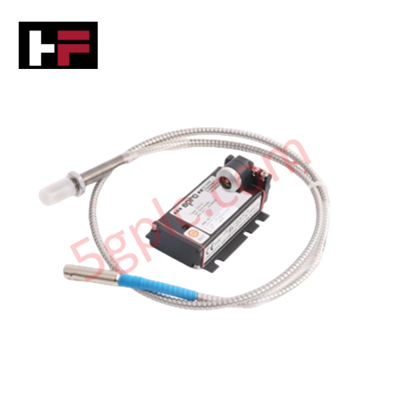
Configured for precision shaft displacement monitoring in rotating machinery, the Epro PR6426/010-140 + CON011/916-120 (PR6426/010-140 Eddy Current Sensor) provides direct physical electrical execution for measuring relative radial and axial shaft vibration. The system utilizes electromagnetic induction to generate a linear voltage output proportional to the gap between the 8 mm probe tip and the observed conductive target, facilitating continuous rotor dynamics assessment via a 120-meter extension cable interface.
Hardware Specifications
| Parameter | Specification |
|---|---|
| Model | PR6426/010-140 + CON011/916-120 |
| Brand | Epro |
| Operating Temp | -35 to 150 deg C (Probe) |
| Power Consumption | -24 V DC (± 1%) |
| Sensitivity | 8.0 V/mm |
| Linear Range | 2.0 mm |
Eddy-Current Probe Scaling and Rotor Dynamics
The PR6426 system is designed to provide linear signal output across the specified transducer measuring range of 2.0 mm. Proper eddy-current probe scaling is required to maintain the accuracy of vibration data when interfaced with monitoring instrumentation. During commissioning, operators must perform a gap voltage validation against the -10 VDC target, ensuring the probe tip is positioned within the linear segment of the transducer's sensitivity curve. This calibration is necessary to capture accurate rotor dynamics, including shaft orbits and eccentricities, while minimizing the influence of cross-talk suppression limitations in multi-probe array configurations.
Frequently Asked Questions (FAQ)
Q: What is the impact of the 120-meter cable length on signal fidelity?
A: The system is designed to compensate for the impedance characteristics of the 120-meter extension cable. Ensure that the specific transducer model matches the cable impedance to prevent signal attenuation and frequency response degradation within the 0 to 10,000 Hz range.
Q: How is the gap voltage validated during site installation?
A: Utilize a high-impedance digital multimeter to measure the output voltage at the monitoring system interface. Adjust the probe distance from the shaft target until the output reads -10 VDC, which corresponds to the midpoint of the linear operating range.
Field Installation Guidelines
- Inspect the 8 mm probe tip for mechanical damage or metallic debris that could introduce non-linearities into the output signal.
- Secure the probe in a rigid mounting bracket to prevent resonant vibrations from contaminating the displacement data.
- Terminate the coaxial cable using the provided CON011 connectors, ensuring all connections are shielded and grounded at the rack entry point to minimize electromagnetic interference.
- Route the 120-meter cable through dedicated, non-metallic conduits if possible to maintain signal integrity and avoid inductive coupling with high-voltage power lines.
- Perform a full-scale static calibration check after installation to confirm that the displacement output remains consistent with target gap measurements.
Additional Information
- 100% Genuine Parts: All products are original and authentic, ensuring reliable industrial performance.
- 30-Day Refund Guarantee: Return any in-stock item within 30 days in original, unopened packaging for a full refund (excluding shipping and fees).
- 12-Month Warranty: Covers defects in materials or workmanship; excludes misuse, normal wear, or unauthorized modifications.
- Worldwide Shipping: We ship via USPS, UPS, FedEx, and DHL. Delivery times vary by country and may be subject to customs or import fees.
- Support & Contact: Technical and warranty assistance is available anytime. Contact us here: Contact.
- Purchase Guidance: Check product specifications and compatibility carefully before ordering to ensure proper application.




Tech & Buying Guide

Voice-Activated Industrial Automation: Integrating Speech Control into PLC and DCS Architectures
Industrial automation integrates speech recognition, IIoT protocols, and NLP with PLCs and DCS to streamline operations. By leveraging advanced edge computing, engineers enable real-time, hands-free control—allowing personnel to manage smart factory processes safely away from hazardous equipment.
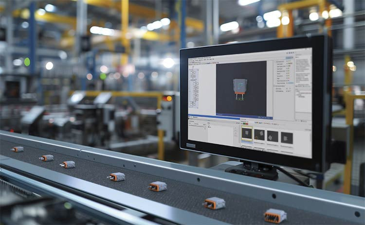
Modern Industrial Automation: Transforming Safety and Efficiency in Mining Operations
Industrial automation has evolved from a simple manufacturing tool into the operational backbone of high-risk sectors. Modern mining operations increasingly rely on advanced control systems, programmable logic controllers (PLCs), distributed control systems (DCS), and artificial intelligence to address deep-underground hazards. By replacing manual labor in high-risk zones, factory automation technologies protect personnel while significantly boosting operational throughput.