


Product Details
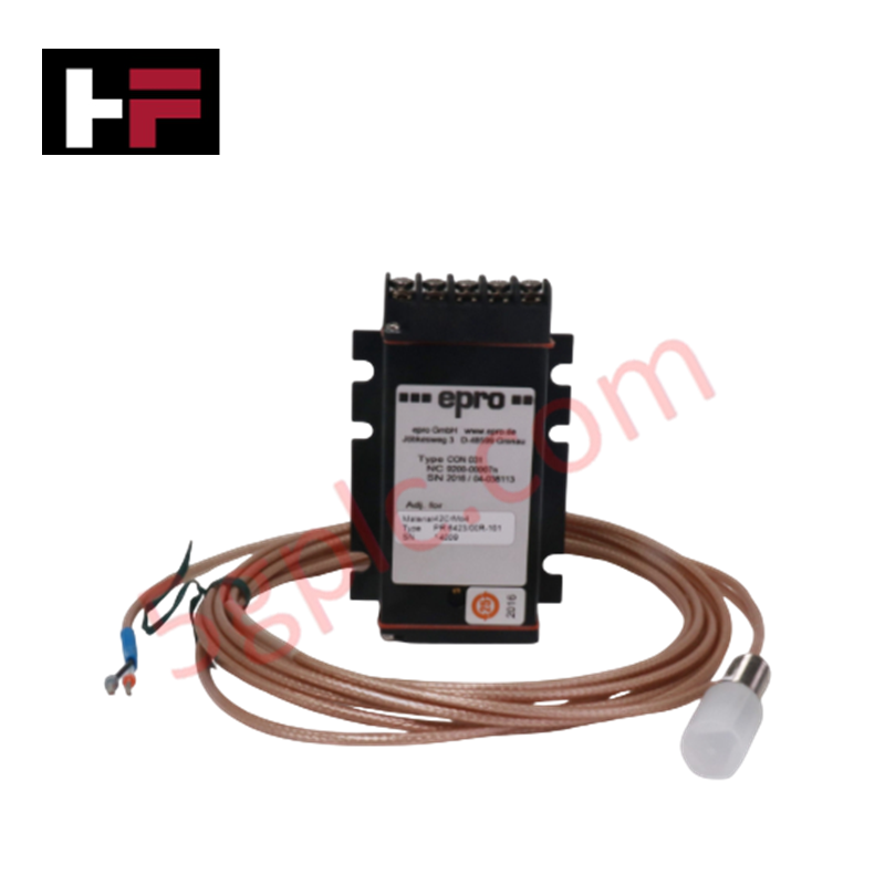
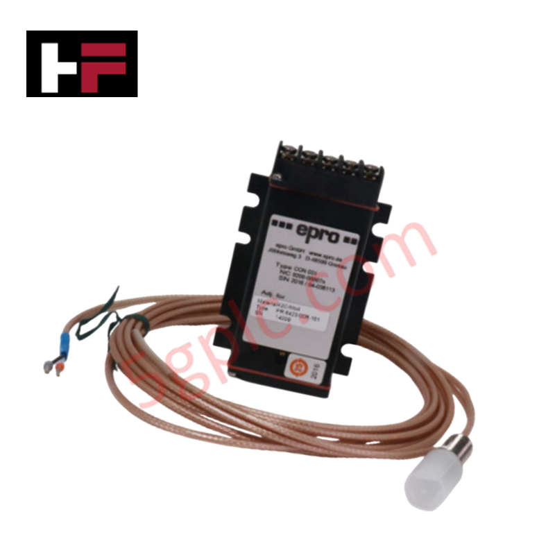
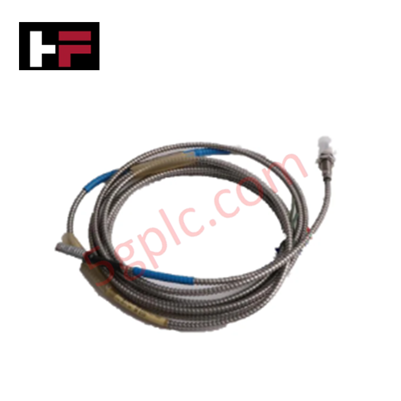
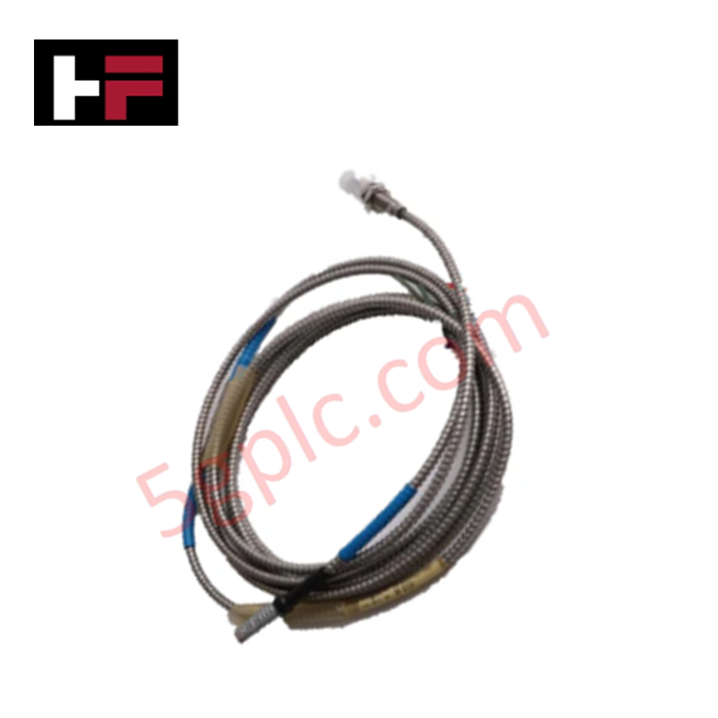
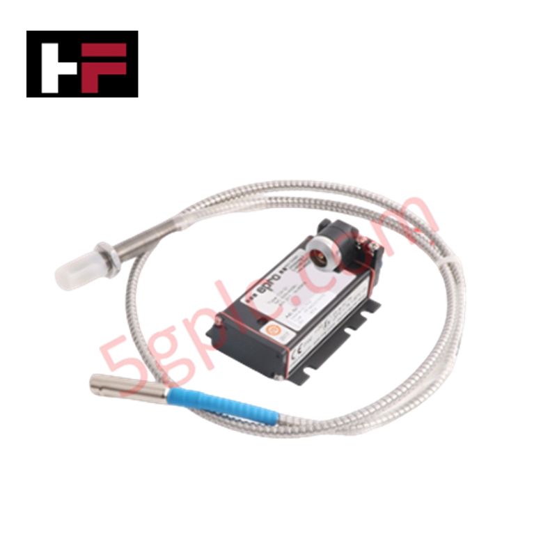
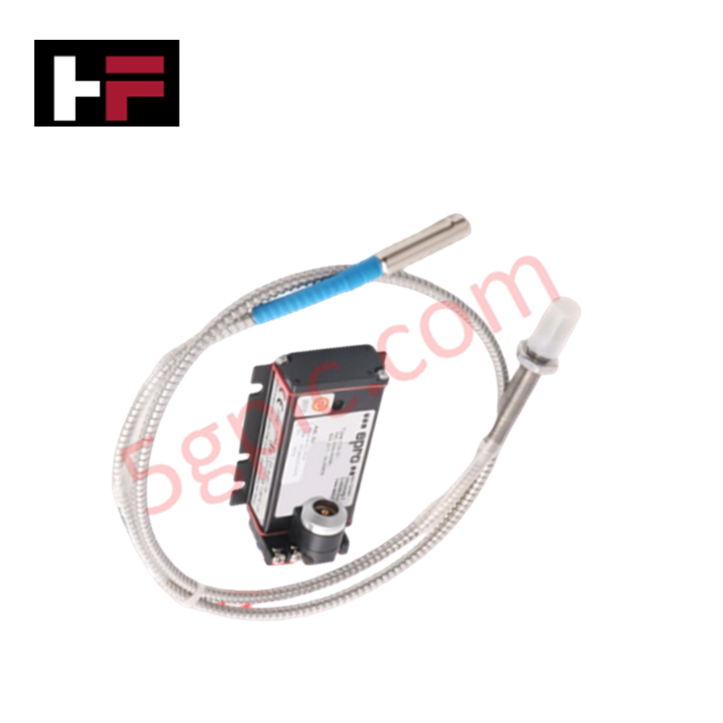
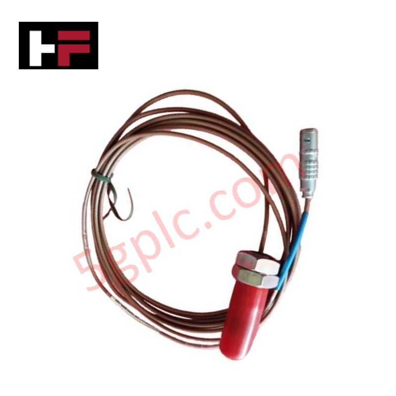
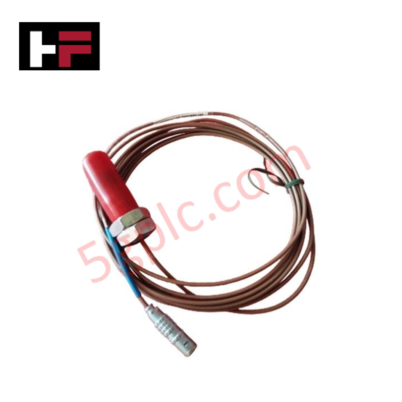
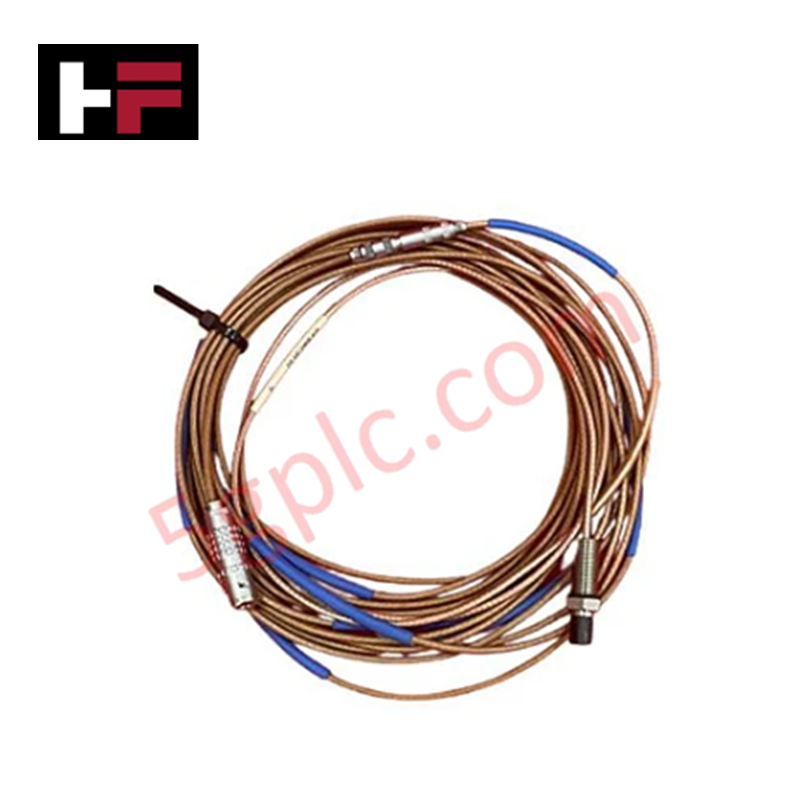
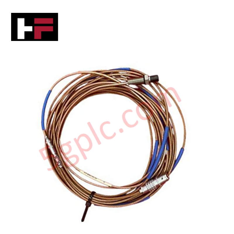
Configured for precision shaft displacement and vibration acquisition in rotating machinery, the Emerson Epro PR6424/01CS (PR6424/01CS) Eddy-current proximity sensor provides direct physical and electrical execution for dynamic position sensing.
Hardware Specifications
| Parameter | Specification |
|---|---|
| Model | PR6424/01CS |
| Brand | Emerson Epro |
| Origin | Germany |
| Dimensions | 16 mm probe diameter |
| Operating Temp | Not specified |
| Power Consumption | System-dependent |
| Sensitivity | 4 V/mm |
| Linear Range | 2.0 mm |
Mechanical Monitoring & Eddy-Current Probe Scaling
The PR6424/01CS sensor is engineered for integration into monitoring chains requiring high-accuracy shaft displacement data. Successful deployment necessitates precise eddy-current probe scaling to align the 4 V/mm output with the specific mechanical displacement of the rotor. During commissioning, gap voltage validation is required to ensure the sensor operates at the nominal gap distance of 2.7 mm, maintaining the output within the linear range of +2.0 mm. For optimal rotor dynamics data acquisition, the shaft surface must consist of ferromagnetic steel (e.g., 204 grade) with a diameter exceeding 80 mm to prevent signal distortion. Cross-talk suppression should be managed by ensuring adequate spacing between multiple probes installed on the same rotor stage, preventing mutual interference between high-frequency oscillator signals.
Frequently Asked Questions
Q: How does the shaft material affect the sensor measurement?
A: The sensor sensitivity is calibrated for specific ferromagnetic materials. Deviations in shaft material permeability or conductivity relative to the factory calibration (e.g., 204 steel) will introduce non-linearities and require secondary calibration curve adjustments.
Q: What is the significance of the 2.7 mm nominal gap distance?
A: The nominal gap defines the center point of the linear operating range. Deviations from this distance will shift the sensor's output away from the center of the -10 VDC target range, potentially leading to signal clipping during high-amplitude vibration events.
Field Installation Guidelines
- Probe Mounting: Secure the sensor in a rigid, vibration-isolated bracket. Ensure the probe tip is perpendicular to the shaft surface to prevent non-linear signal responses.
- Gap Setting: Use a non-conductive feeler gauge or a micrometer to set the nominal gap distance to 2.7 mm relative to the shaft surface at the intended measurement location.
- Cable Integrity: Route the sensor lead in dedicated instrumentation conduit, separated from AC power lines. Utilize shielded cables to protect the low-level signal from induced electromagnetic interference.
- Shielding: Terminate cable shields at a single-point instrumentation ground at the signal conditioner end to prevent ground loops.
- System Validation: Power the monitoring loop and verify the DC output voltage at the signal conditioner input. Confirm that the measured voltage corresponds to the nominal gap distance before allowing the machinery to rotate.
Additional Information
- 100% Genuine Parts: All products are original and authentic, ensuring reliable industrial performance.
- 30-Day Refund Guarantee: Return any in-stock item within 30 days in original, unopened packaging for a full refund (excluding shipping and fees).
- 12-Month Warranty: Covers defects in materials or workmanship; excludes misuse, normal wear, or unauthorized modifications.
- Worldwide Shipping: We ship via USPS, UPS, FedEx, and DHL. Delivery times vary by country and may be subject to customs or import fees.
- Support & Contact: Technical and warranty assistance is available anytime. Contact us here: Contact.
- Purchase Guidance: Check product specifications and compatibility carefully before ordering to ensure proper application.


Tech & Buying Guide

Strategic Selection: Choosing the Right SCADA Software for Your PLC Project
In industrial automation, the SCADA (Supervisory Control and Data Acquisition) system acts as the bridge between raw machine data and actionable human intelligence. Selecting the incorrect software platform can lead to integration bottlenecks, scalability issues, and excessive long-term maintenance costs. As an automation consultant with 15 years of experience, I have guided many projects through the selection process. Below are the essential criteria for choosing a platform that ensures both performance and longevity.

Ensuring Operational Continuity: The Strategic Value of Redundant Automation Systems
In modern industrial landscapes, unplanned downtime is the ultimate adversary. For sectors relying on complex PLC and DCS architectures, a single hardware failure can trigger catastrophic production losses. Therefore, implementing redundant automation systems is no longer a luxury; it is a fundamental requirement for mission-critical operations. In this article, I analyze why redundancy remains the backbone of reliable industrial infrastructure.

Selecting the Right Cables for Industrial Automation: A Comprehensive Guide
Selecting the appropriate cabling infrastructure is critical for the success of any industrial automation project. Improper cable selection often leads to signal degradation, system instability, and costly downtime. As an automation engineer, I frequently see projects compromised by poor cabling choices in harsh industrial environments. This guide simplifies the complex landscape of cabling to help you make informed decisions for your PLC, DCS, and control systems.