










Product Details
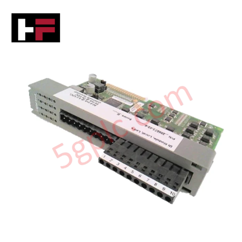
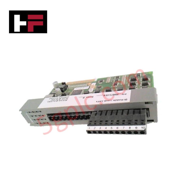
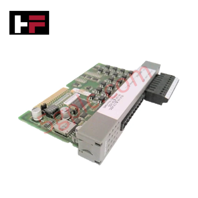
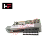
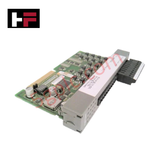
The Emerson 396571-02-6, also cataloged as the 396571 Isolated Input Module, operates as a dedicated hardware component for galvanic signal conditioning and field contact state detection within ControlWave PLC platforms. Equipped with a 24 V local connector and an integrated LED daughterboard, it processes field input signals while maintaining electrical isolation from internal backplane logic.
Hardware Specifications
| Parameter | Specification |
|---|---|
| Model | 396571-02-6 |
| Brand | Emerson |
| Base Model | 396571 |
| Origin | USA |
| Weight | 0.26 lbs (approx. 0.12 kg) |
| Dimensions | Standard ControlWave Micro Module Footprint |
| Operating Temp | -40 to 70 deg C |
| Power Consumption | 24 VDC Local Connector Powered |
| Signal Isolation | Isolated Field Circuits |
| Local Indication | Onboard LED Daughterboard |
| System Compatibility | ControlWave PLC Series |
4-20 mA HART Loop Protocol and Channel Isolation
The 396571-02-6 module incorporates optical channel-to-channel isolation architecture to decouple field-side transients from the internal system bus. This isolation structure suppresses common-mode voltage spikes, ground loops, and electrical cross-talk, preventing signal degradation across neighboring analog circuits running 4-20 mA HART loop protocol signals on the same backplane assembly.
Frequently Asked Questions
Q: What function does the integrated LED daughterboard serve on the 396571-02-6 module?
A: The onboard LED daughterboard provides real-time local visual status indication for channel input state activity and diagnostic hardware conditions.
Q: How is local power supplied to the input circuitry of the 396571-02-6?
A: The module utilizes a dedicated 24 V local connector interface to deliver isolated operating voltage directly to field input sensing circuits.
Q: Can the 396571-02-6 module be hot-swapped during system operation?
A: Hot-swapping limits depend on the specific ControlWave rack chassis configuration; field power to the 24 V local connector should be isolated prior to module removal to avoid arc discharge.
Field Installation Guidelines
- Power down field-side 24 V power connections before seating or unseating the module from the ControlWave backplane chassis.
- Align the module circuit board with the chassis guide rails and push firmly until the backplane connector engages completely.
- Tighten the retaining panel fasteners to establish frame grounding contact and secure the assembly against vibration.
- Wire 24 V local input power and field signal leads to the designated terminal header, ensuring proper polarity.
- Ground field cable shielding at a single grounding point on the enclosure chassis to minimize electromagnetic noise coupling.
Additional Information
- 100% Genuine Parts: All products are original and authentic, ensuring reliable industrial performance.
- 30-Day Refund Guarantee: Return any in-stock item within 30 days in original, unopened packaging for a full refund (excluding shipping and fees).
- 12-Month Warranty: Covers defects in materials or workmanship; excludes misuse, normal wear, or unauthorized modifications.
- Worldwide Shipping: We ship via USPS, UPS, FedEx, and DHL. Delivery times vary by country and may be subject to customs or import fees.
- Support & Contact: Technical and warranty assistance is available anytime. Contact us here: Contact.
- Purchase Guidance: Check product specifications and compatibility carefully before ordering to ensure proper application.




Tech & Buying Guide

Understanding Siemens PLC Memory Cards: MMC, SMC, and SD Solutions in Industrial Automation
Memory management plays a pivotal role in maintaining control system reliability across modern manufacturing plants. Industrial control systems rely on specialized memory cards to store project logic, firmware updates, and retentive system data. Siemens uses several memory architectures, including Micro Memory Cards (MMC) and SIMATIC Memory Cards (SMC). Engineers must understand these hardware variations to ensure zero data loss and minimize downtime during maintenance routines.

Redefining Control Systems: The Rise of Flexible I/O Modules in Industrial Automation
Conventional input-output architectures often limit engineering agility and inflate long-term inventory costs. Today, Flexible Input/Output Modules (FIOM) are transforming how control system engineers design, commission, and maintain automation infrastructure. By allowing individual channel software configuration, FIOM technology bridges the gap between rigid hardware design and dynamic plant requirements.

Understanding Modern SCADA Systems: Architecture, Communication Topologies, and Industrial Applications
Supervisory Control and Data Acquisition (SCADA) systems form the digital backbone of modern industrial automation. They collect critical field data, transmit signals across vast distances, and empower plant operators with real-time process visibility. Across modern infrastructures, SCADA solutions streamline centralized control and maintain continuous operational uptime.