










Product Details
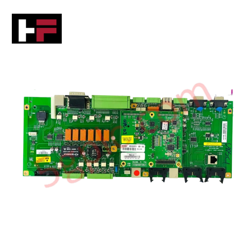
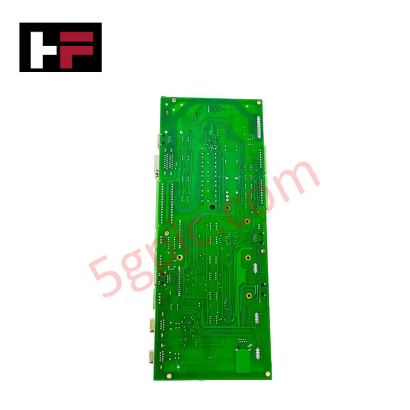
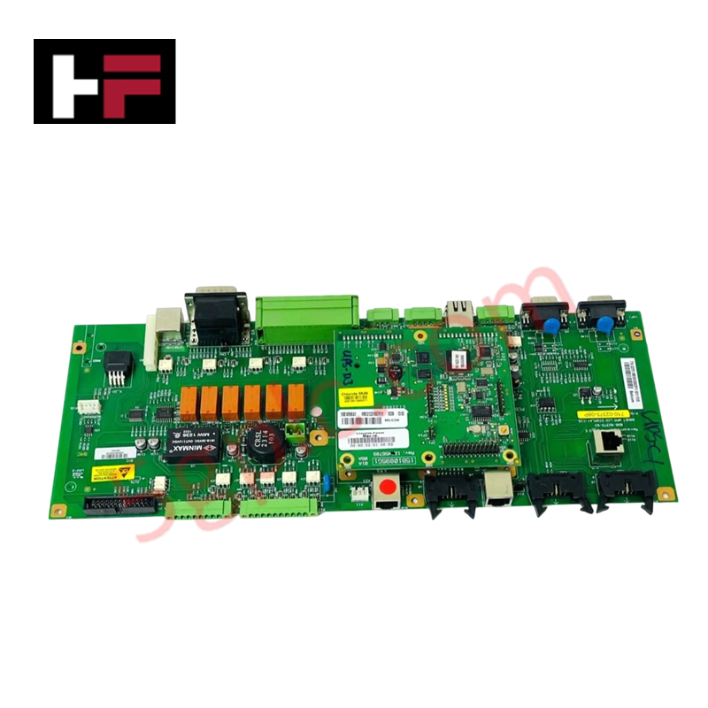
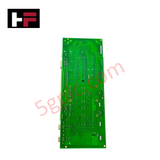
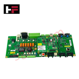
The Emerson 15B10895G1, also cataloged as the 15B10895G1 Network Power Board, operates as a dedicated hardware component for alternating current line conversion and direct voltage regulation within industrial control networks. It accepts primary utility power inputs to deliver continuous DC operational potentials to control backplane assemblies.
Hardware Specifications
| Parameter | Specification |
|---|---|
| Model | 15B10895G1 |
| Brand | Emerson |
| Base Model | 15B10895G1 |
| Origin | USA |
| Weight | 0.2 lbs (0.09 kg) |
| Dimensions | 2.5 cm x 27.9 cm x 25.4 cm |
| Operating Temp | -40 to +60 deg C (-40 to +140 deg F) |
| Power Consumption | Standard internal board draw |
| Input Voltage | 100-240 V AC |
| Relative Humidity | 5% to 95% non-condensing |
| Airborne Contaminants | ISA-S71.04-1985 Class G3 |
| Shock Resistance | 10 g half-sine wave for 11 ms |
| Vibration Resistance | 1 mm peak-to-peak (2 to 13.2 Hz), 0.7 g (13.2 to 150 Hz) |
4-20 mA HART Loop Protocol and Channel-to-Channel Isolation
The 15B10895G1 circuit board incorporates galvanic isolation barriers between its AC input terminals and low-voltage internal distribution buses. This physical separation prevents line-side common-mode noise, ground loops, and high-voltage surges from propagating into sensitive analog field processing loops, preserving baseline signal fidelity for connected 4-20 mA HART loop protocol instruments across system segments.
Frequently Asked Questions
Q: What line input voltage range does the 15B10895G1 circuit board accept?
A: The board operates across a wide AC supply range of 100-240 V AC without requiring manual voltage tap adjustments.
Q: Is the 15B10895G1 circuit board suitable for corrosive field enclosure environments?
A: Yes, the board meets ISA-S71.04-1985 Class G3 specifications for resistance against airborne chemical contaminants.
Q: Can the board withstand standard industrial enclosure vibration profiles?
A: The board is rated for 1 mm peak-to-peak displacement from 2 to 13.2 Hz and 0.7 g acceleration from 13.2 to 150 Hz.
Field Installation Guidelines
- Disconnect and lock out primary AC mains voltage prior to mounting or servicing the circuit board assembly.
- Verify board orientation and align mounting standoffs or card edge guides within the chassis frame before fully seating the board.
- Fasten all retention screws to specified torque limits to establish mechanical stability against ambient vibration.
- Connect incoming AC lines to designated screw terminals, ensuring protective earth grounding leads are firmly terminated.
- Inspect input power line fusing and verify clean terminal connections before restoring AC utility power.
Additional Information
- 100% Genuine Parts: All products are original and authentic, ensuring reliable industrial performance.
- 30-Day Refund Guarantee: Return any in-stock item within 30 days in original, unopened packaging for a full refund (excluding shipping and fees).
- 12-Month Warranty: Covers defects in materials or workmanship; excludes misuse, normal wear, or unauthorized modifications.
- Worldwide Shipping: We ship via USPS, UPS, FedEx, and DHL. Delivery times vary by country and may be subject to customs or import fees.
- Support & Contact: Technical and warranty assistance is available anytime. Contact us here: Contact.
- Purchase Guidance: Check product specifications and compatibility carefully before ordering to ensure proper application.


Tech & Buying Guide

Demystifying Open Platform Communication (OPC): The Backbone of Industrial Interoperability
Interoperability remains a cornerstone requirement for modern smart factories and process automation. Open Platform Communication (OPC) bridges the gap between disparate hardware platforms, control systems, and visualization software. By establishing a universal communication standard, OPC allows field controllers, SCADA platforms, and enterprise software from different vendors to exchange real-time data seamlessly.

Understanding Siemens PLC Memory Cards: MMC, SMC, and SD Solutions in Industrial Automation
Memory management plays a pivotal role in maintaining control system reliability across modern manufacturing plants. Industrial control systems rely on specialized memory cards to store project logic, firmware updates, and retentive system data. Siemens uses several memory architectures, including Micro Memory Cards (MMC) and SIMATIC Memory Cards (SMC). Engineers must understand these hardware variations to ensure zero data loss and minimize downtime during maintenance routines.

Redefining Control Systems: The Rise of Flexible I/O Modules in Industrial Automation
Conventional input-output architectures often limit engineering agility and inflate long-term inventory costs. Today, Flexible Input/Output Modules (FIOM) are transforming how control system engineers design, commission, and maintain automation infrastructure. By allowing individual channel software configuration, FIOM technology bridges the gap between rigid hardware design and dynamic plant requirements.