


Product Details
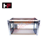
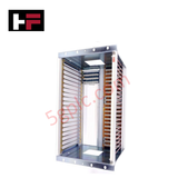
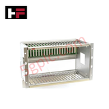
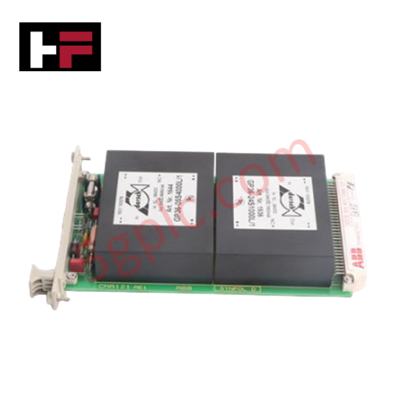
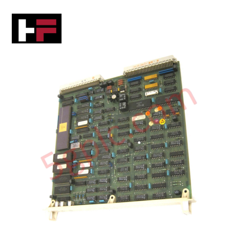
The ABB DSRF 170 57310255-AC serves as the primary DSRF 170 Equipment Frame utilized to execute structural module housing and backplane power distribution across MasterPiece platforms. The subrack provides direct physical alignment and multi-slot retention rails for active electronic plug-in cards, keeping internal wiring paths mechanically bound within exact tolerances.
Hardware Specifications
| Parameter | Specification |
|---|---|
| Model | DSRF 170 |
| Brand | ABB |
| Product ID | 57310255-AC |
| Origin | Sweden |
| Weight | 8.0 kg net |
| Dimensions | Standard subrack layout (Optimized for standard industrial cubicle mounting) |
| Operating Temp | 0 to +55 deg C (Standard environment baseline) |
| Power Consumption | Passive chassis architecture (Distributes localized power rail loads) |
| Core Function | Circuit board orientation, mechanical card slot retention, and backplane tracking |
| Construction Type | Open subrack frame configuration |
Deterministic Networks & I/O Density Scaling
The structural footprint dictates the physical capacity boundary for localized I/O density scaling inside the automation cubicle. Circuit traces within the integrated backplane coordinate digital packets over Profinet / EtherNet/IP deterministic networks by ensuring structural trace impedance matching. This multi-slot structural layout prevents geometric deflection of rear connector pins, preserving deterministic data scan cycles and maintaining firmware flash compatibility handshakes between adjacent active processing elements.
Frequently Asked Questions
Q: Does the structural layout of the DSRF 170 allow live hot-swap execution of active cards?
A: The DSRF 170 is a passive mechanical enclosure with bus infrastructure. Live component extraction or insertion dependencies reside purely on the active electrical modules and terminal interfaces configured inside the subrack.
Q: How is the common reference potential bonded across separate card slots on the chassis?
A: Frame structural pieces are mechanically bridged to a copper grounding block located at the rear of the assembly. This terminal must be linked to the primary enclosure earth to establish common grounding paths.
Q: What physical faults result from unexpected mechanical warping of the module rails?
A: Mechanical distortion of the guide tracks causes uneven contact terminal stress at the backplane interface, increasing capacitance variation and causing signal packet drops across the internal communications network.
Field Installation Guidelines
- Bolt the frame housing securely onto the cabinet matrix assembly, verifying parallel plane orientation to prevent mechanical strain on the subrack components.
- Maintain an open vertical clearance zone of at least 100 mm above and below the chassis border to allow free thermal air draft flow from active circuits.
- Establish a distinct low-impedance connection between the primary chassis ground stud and the master enclosure copper earth bar using a heavy-gauge braid before powering active components.
- Ensure all card retention fasteners are manually secured after card insertion to damp mechanical vibration components in long-term operation.
Additional Information
- 100% Genuine Parts: All products are original and authentic, ensuring reliable industrial performance.
- 30-Day Refund Guarantee: Return any in-stock item within 30 days in original, unopened packaging for a full refund (excluding shipping and fees).
- 12-Month Warranty: Covers defects in materials or workmanship; excludes misuse, normal wear, or unauthorized modifications.
- Worldwide Shipping: We ship via USPS, UPS, FedEx, and DHL. Delivery times vary by country and may be subject to customs or import fees.
- Support & Contact: Technical and warranty assistance is available anytime. Contact us here: Contact.
- Purchase Guidance: Check product specifications and compatibility carefully before ordering to ensure proper application.
Tech & Buying Guide

Core Components of Programmable Logic Controllers (PLC) in Industrial Automation
A Programmable Logic Controller (PLC) serves as the digital backbone of modern factory automation. Whether you are managing complex assembly lines or simple process loops, understanding the hardware and software architecture of a PLC is essential for any control systems engineer.

PLC vs. PC: Navigating the Architectural Differences in Industrial Automation
In the realm of factory automation, professionals often debate the roles of Programmable Logic Controllers (PLCs) and Personal Computers (PCs). While both devices share fundamental computing architectures—including a processor, memory, and an operating system—their design philosophies diverge significantly. Understanding these distinctions is critical for selecting the right hardware for your industrial control systems.

Essential SCADA Features for Modern IoT-Enabled Industrial Automation
The convergence of traditional SCADA systems with the Industrial Internet of Things (IIoT) has redefined factory automation. Choosing a robust platform requires more than just standard monitoring capabilities. In this era of Industry 4.0, your supervisory system must bridge the gap between legacy control systems and enterprise-level data integration.