


Product Details
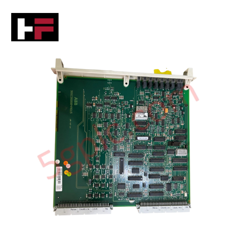
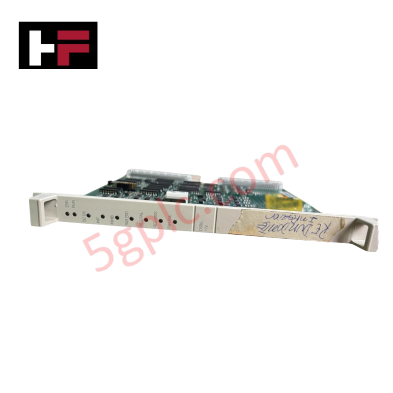
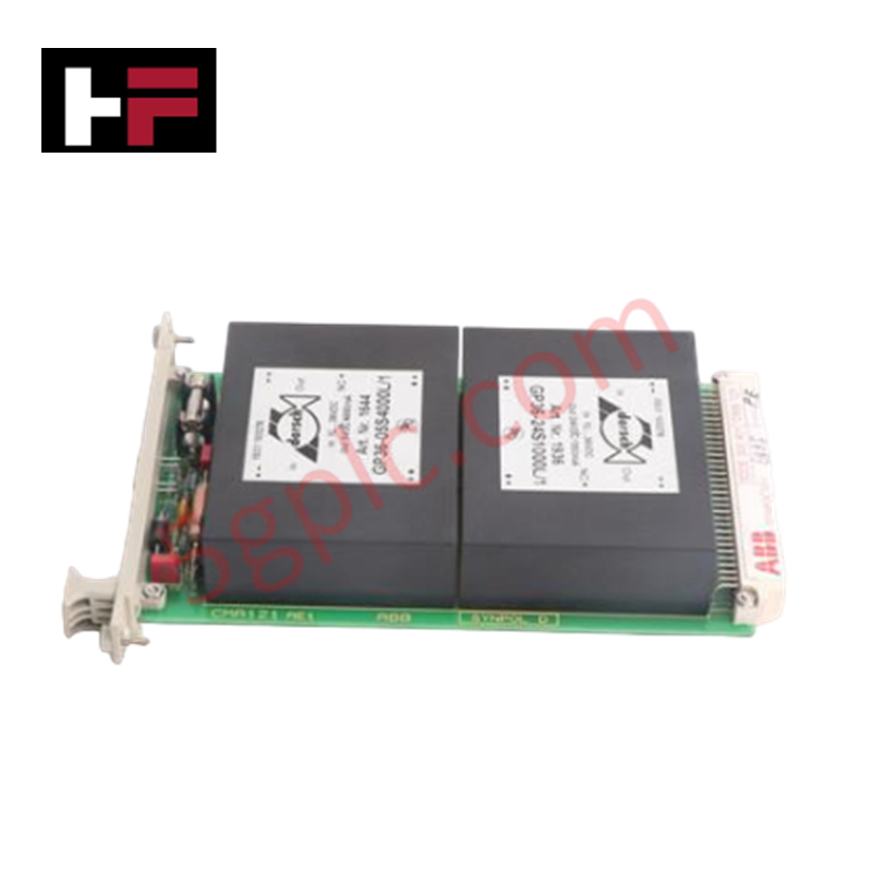
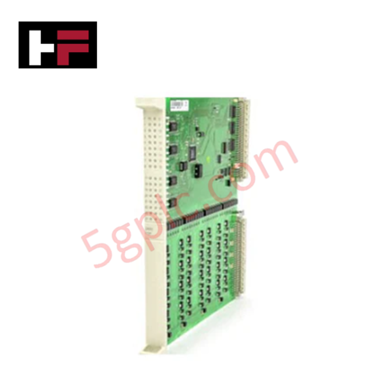
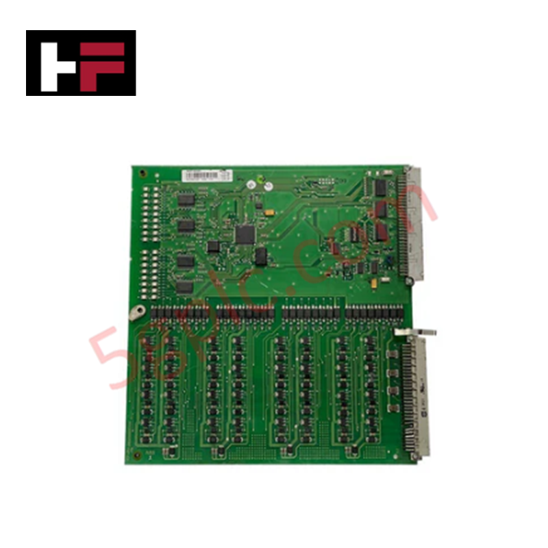
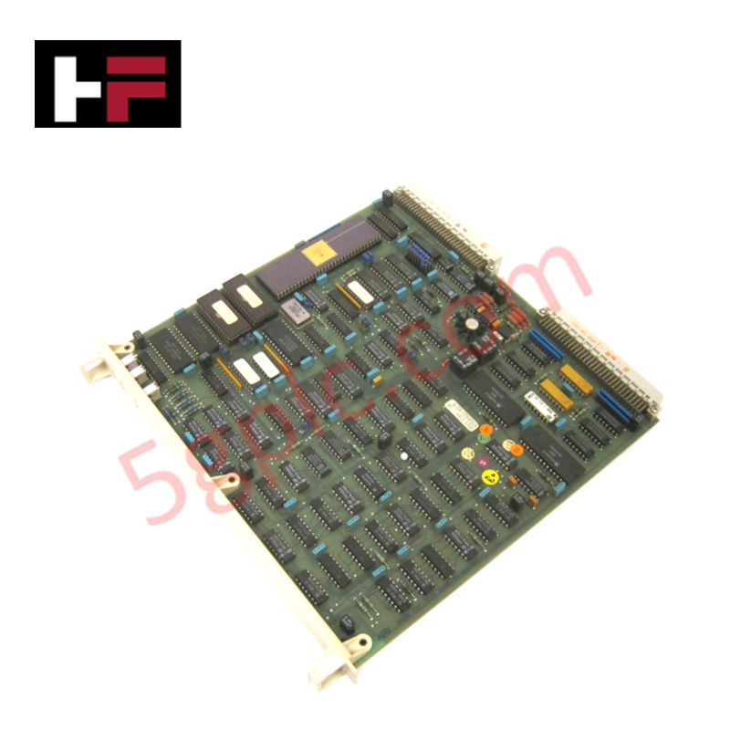
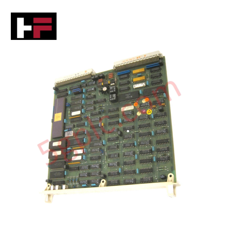
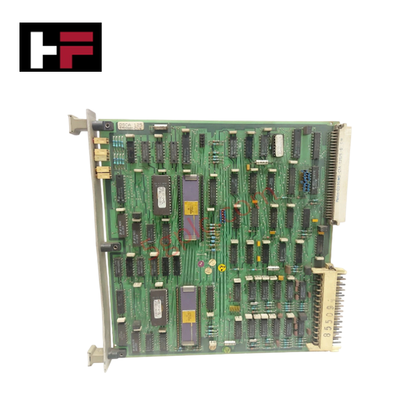
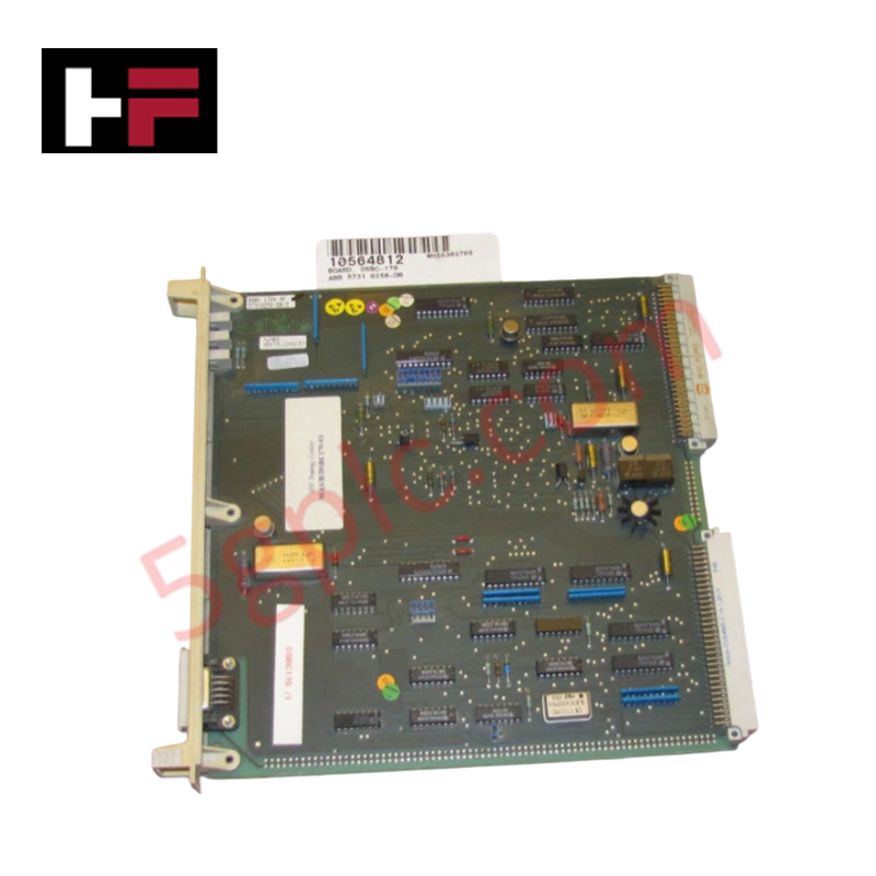
The ABB 3BSE019216R1, also cataloged as the DSBC 176 Bus Extender Board, operates as a dedicated hardware component for physical bus line expansion within Advant Master process control systems. Configured for high-speed parallel signal transmission across split-rack subassemblies, the unit provides direct physical/electrical execution of data buffering tasks to extend communication reach over physical backplane segments.
Hardware Specifications
| Parameter | Specification |
|---|---|
| Model | DSBC 176 |
| Brand | ABB |
| Product ID | 3BSE019216R1 |
| Origin | Sweden |
| Weight | 0.4 kg net |
| Dimensions | 234 mm x 22.5 mm x 324 mm (W x H x D) |
| Operating Temp | 0 to +55 deg C (Standard backplane deployment baseline) |
| Power Consumption | Maintained via system subrack power distribution rails |
| Core Performance | Low-latency signal replication and physical bus expansion |
Deterministic Networks & Firmware Compatibility
The module functions directly within the chassis assembly to manage signal propagation constraints over extended copper links. Parallel data processing profiles map onto timing registers governed by explicit backplane bus communication velocity licenses. This structural hardware interface stabilizes communications across Profinet / EtherNet/IP deterministic networks, maintaining critical synchronization clocks and firmware flash compatibility parameters between primary processing elements and distributed multi-channel clusters without compounding throughput latency under conditions of peak I/O density scaling.
Frequently Asked Questions
Q: Does the DSBC 176 module support active extraction or live hot-swapping procedures?
A: No. S500 and Advant Master rack design restrictions mandate that the subrack power distribution assembly must be fully isolated before inserting or extracting the board to prevent critical transceiver damage or unintended bus faults.
Q: How is the characteristic line impedance balanced when extending the backplane bus?
A: Physical termination blocks must be applied at the outer physical boundaries of the expanded bus configuration, matching the electrical specifications of the short-distance cable links.
Q: What indicates a failure in firmware flash compatibility during module integration?
A: The master system controller will register a backplane initialization block, dropping communication connection frames to the extender board and suppressing remote I/O processing cycles.
Field Installation Guidelines
- Insert the board smoothly along the assigned slot tracks of the chassis cage, ensuring proper pin mating with the rear backplane connector before finalizing mechanical engagement.
- Maintain a minimum separation boundary of 100 mm between external bus extension cables and local high-voltage AC electrical distribution runs inside the cabinet enclosure.
- Terminate all external network shield braids directly at the central low-resistance panel copper ground strip to block industrial high-frequency electromagnetic interference.
- Secure the front-facing retention thumb fasteners manually to damp structural vibration components and prevent contact resistance spikes over long operating intervals.
Additional Information
- 100% Genuine Parts: All products are original and authentic, ensuring reliable industrial performance.
- 30-Day Refund Guarantee: Return any in-stock item within 30 days in original, unopened packaging for a full refund (excluding shipping and fees).
- 12-Month Warranty: Covers defects in materials or workmanship; excludes misuse, normal wear, or unauthorized modifications.
- Worldwide Shipping: We ship via USPS, UPS, FedEx, and DHL. Delivery times vary by country and may be subject to customs or import fees.
- Support & Contact: Technical and warranty assistance is available anytime. Contact us here: Contact.
- Purchase Guidance: Check product specifications and compatibility carefully before ordering to ensure proper application.
Tech & Buying Guide

Core Components of Programmable Logic Controllers (PLC) in Industrial Automation
A Programmable Logic Controller (PLC) serves as the digital backbone of modern factory automation. Whether you are managing complex assembly lines or simple process loops, understanding the hardware and software architecture of a PLC is essential for any control systems engineer.

PLC vs. PC: Navigating the Architectural Differences in Industrial Automation
In the realm of factory automation, professionals often debate the roles of Programmable Logic Controllers (PLCs) and Personal Computers (PCs). While both devices share fundamental computing architectures—including a processor, memory, and an operating system—their design philosophies diverge significantly. Understanding these distinctions is critical for selecting the right hardware for your industrial control systems.

Essential SCADA Features for Modern IoT-Enabled Industrial Automation
The convergence of traditional SCADA systems with the Industrial Internet of Things (IIoT) has redefined factory automation. Choosing a robust platform requires more than just standard monitoring capabilities. In this era of Industry 4.0, your supervisory system must bridge the gap between legacy control systems and enterprise-level data integration.