


Product Details
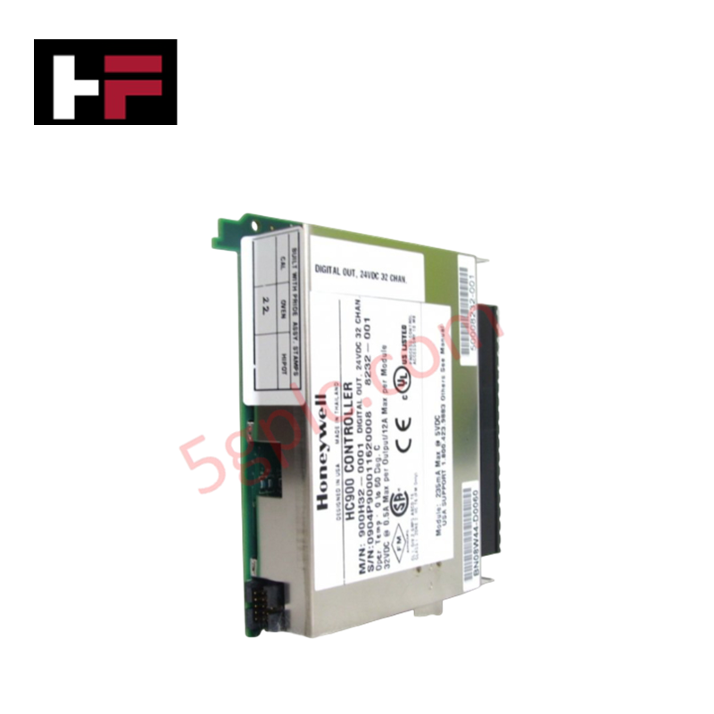
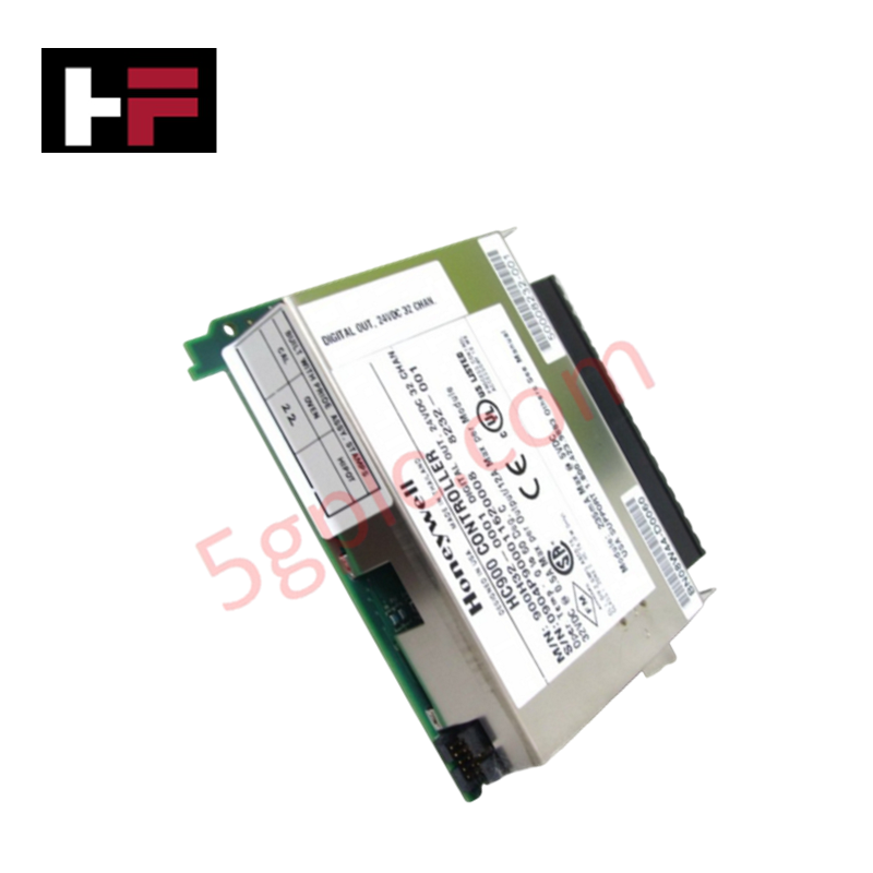
Configured for high-density digital signal control in Experion Series C I/O platforms, the Honeywell DC-PDOD51 (DC-PDOD51) Digital Output Module provides direct physical/electrical execution of 32 independent output channels. The module utilizes Form C dry contact relay architecture to drive field actuators, including valves, pumps, and alarm indicators, operating at a nominal 24 V DC with a maximum load capacity of 0.5 A per channel.
Hardware Specifications
| Parameter | Specification |
|---|---|
| Model | DC-PDOD51 |
| Brand | Honeywell |
| Dimensions | Standard Series C I/O form factor |
| Operating Temp | Consult Experion system manual |
| Power Consumption | Dependent on host I/O load |
| Output Channels | 32 channels |
| Output Type | Form C dry contact |
Channel-to-Channel Isolation
The DC-PDOD51 module is engineered with a 1500 V isolation barrier between the output channels and the internal power supply. This dielectric separation is mandatory to prevent common-mode noise propagation and to protect the controller backplane from field-side voltage transients. By segregating each channel's switching logic from the system bus, the module ensures that localized faults or inductive spikes originating from field-connected solenoids and motors do not compromise the integrity of adjacent channels or the central processor.
Frequently Asked Questions
Q: Does this module support hot-swapping within an active Experion Series C chassis?
A: Yes, the Series C I/O architecture supports hot-swapping of the DC-PDOD51 module. Ensure the module is properly seated and locked into the carrier assembly to re-establish backplane communication without cycling the rack power.
Q: Are the Form C contacts rated for inductive or resistive loads?
A: The Form C contacts are designed for standard industrial control loads. When switching highly inductive loads (e.g., large solenoid valves), ensure proper external arc suppression circuitry is employed to protect the relay contact life.
Field Installation Guidelines
- DIN-Rail Mounting: Secure the module carrier to the DIN-rail using the integrated locking mechanism. Ensure the rail is bonded to the cabinet earth ground to maintain the integrity of the module’s EMI shielding.
- Wiring and Termination: Utilize shielded multi-core cables for field output wiring. Terminate cable shields at the designated ground bar within the cabinet to minimize electromagnetic interference coupling.
- Output Load Management: Verify that the total current draw does not exceed the 0.5 A per-channel limit. For loads exceeding this rating, utilize interposing relays to drive the high-current device.
- Segregation: Route field-side output wiring through dedicated signal ducts, maintaining a minimum distance of 150 mm from high-voltage power lines to prevent induced noise and cross-talk.
Additional Information
- 100% Genuine Parts: All products are original and authentic, ensuring reliable industrial performance.
- 30-Day Refund Guarantee: Return any in-stock item within 30 days in original, unopened packaging for a full refund (excluding shipping and fees).
- 12-Month Warranty: Covers defects in materials or workmanship; excludes misuse, normal wear, or unauthorized modifications.
- Worldwide Shipping: We ship via USPS, UPS, FedEx, and DHL. Delivery times vary by country and may be subject to customs or import fees.
- Support & Contact: Technical and warranty assistance is available anytime. Contact us here: Contact.
- Purchase Guidance: Check product specifications and compatibility carefully before ordering to ensure proper application.


Tech & Buying Guide

Mastering Modern Industrial Joystick Controls in Heavy Automation
Industrial joysticks play a pivotal role in human-machine interaction across heavy material handling and mobile hydraulics. These tactile controllers translate complex operator movements into precise electrical signals for PLCs, motion controllers, and DCS networks. Consequently, selecting and installing the right joystick architecture ensures operator safety, reduces fatigue, and optimizes equipment performance.

Navigating Industrial Automation Failures: Types, Causes, and Mitigation Strategies
Modern manufacturing relies heavily on automated control systems to maximize throughput and maintain product quality. However, unplanned downtime in industrial automation can cost facility operators thousands of dollars per hour. Understanding how programmable logic controllers (PLCs), distributed control systems (DCS), and field instrumentation fail empowers engineering teams to implement robust preventive maintenance strategies.

Essential Motion Control Commands: A Practical Guide for Engineers
Automation engineers often rely on precise position and speed control to drive modern factory machinery. Modern industrial systems, such as Programmable Logic Controllers (PLCs) and Distributed Control Systems (DCS), depend heavily on standardized motion instructions. Mastering these commands ensures operational safety, protects mechanical components, and optimizes cycle times across production lines.