


Product Details
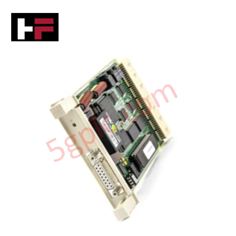
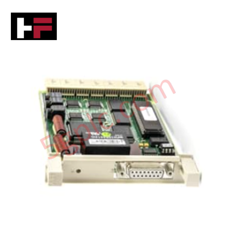
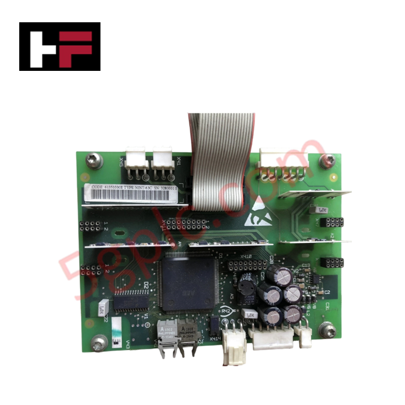
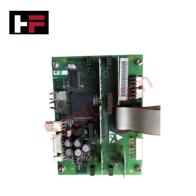
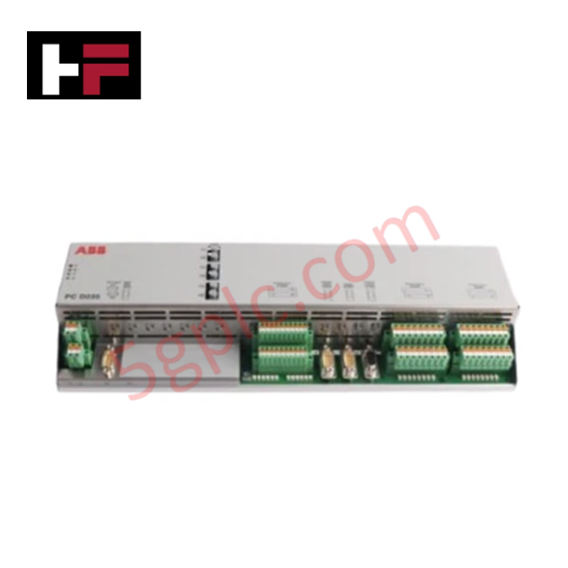
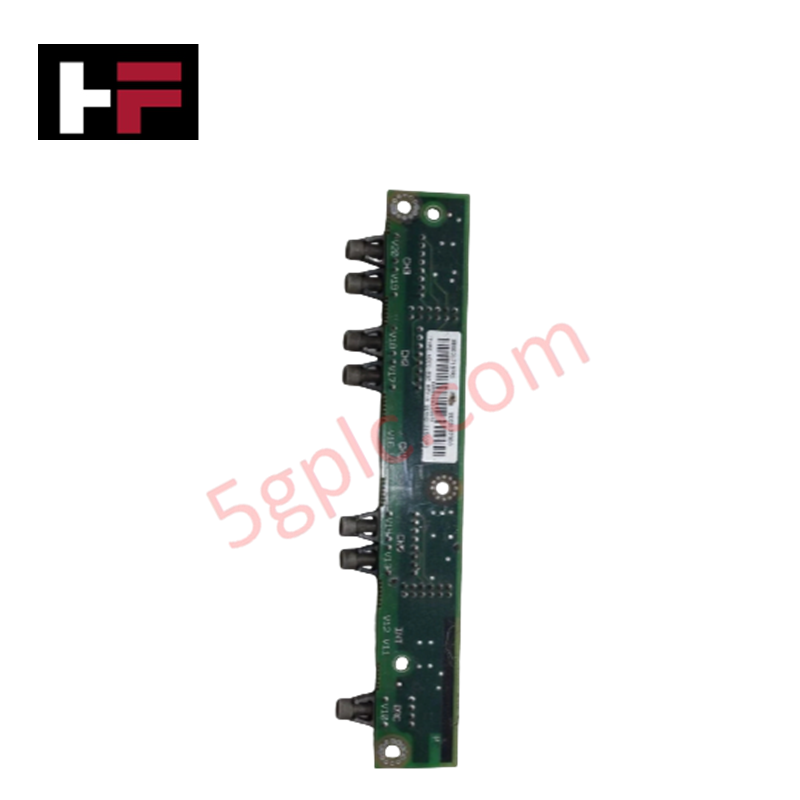
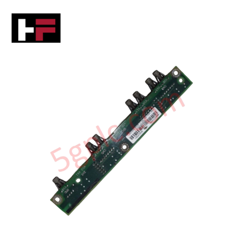
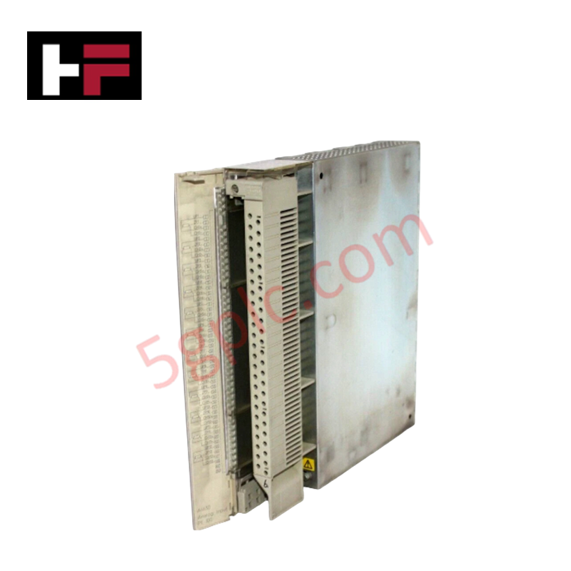
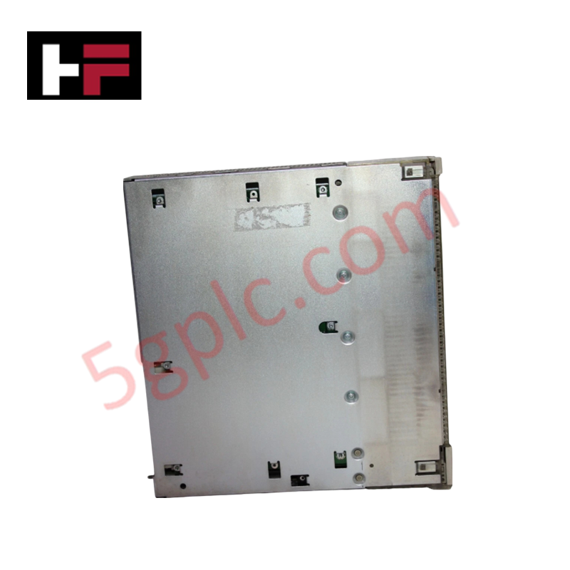
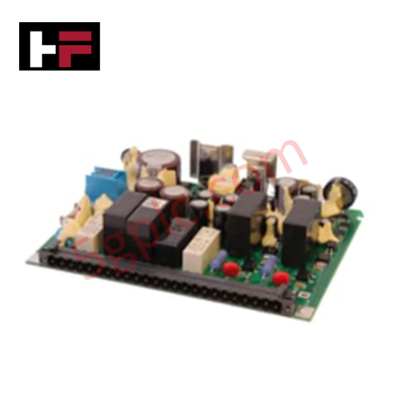
Configured for distributed control network interfacing in industrial automation structures, the ABB CS512 3BUR980009R1 (CS512 Communication Module) provides direct physical/electrical execution.
Hardware Specifications
| Parameter | Specification |
|---|---|
| Model | CS512 3BUR980009R1 |
| Brand | ABB |
| Origin | Sweden / Europe standard sourcing |
| Weight | 0.19 kg |
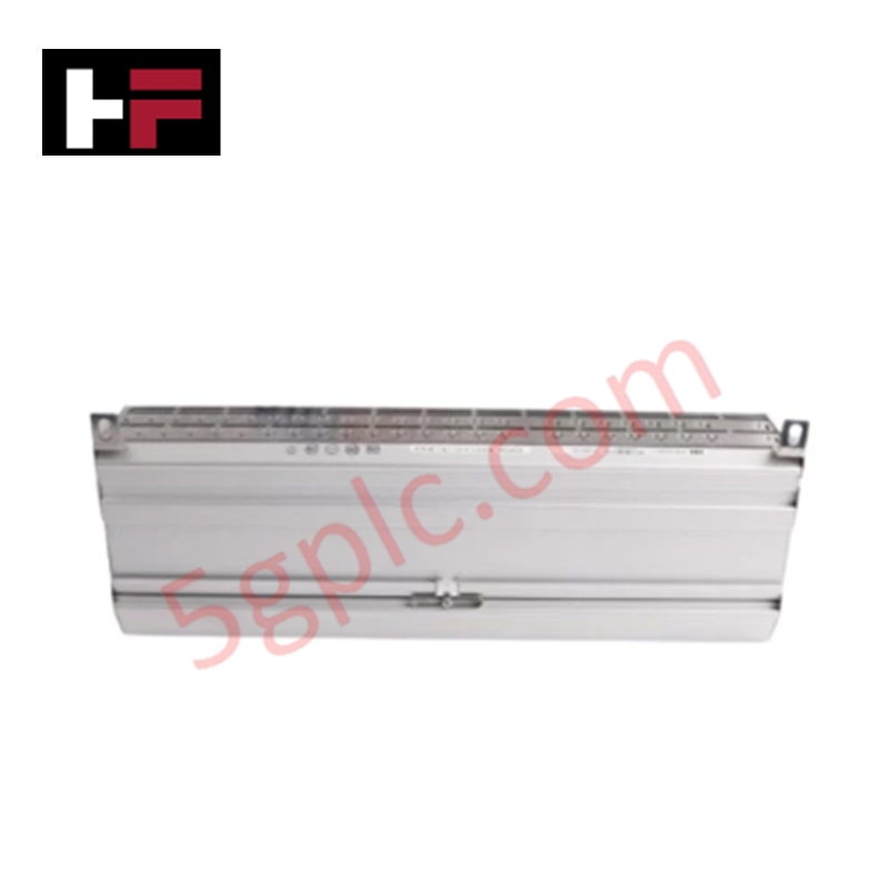
| Dimensions | 260 mm x 25 mm x 115 mm |
| Operating Temp | 0 to 60 deg C standard industrial operating spectrum |
| Power Consumption | Bus-powered via backplane matrix |
| Product Type | Communication Modules |
| Interface Protocol | Distributed Control Network (DCN) Protocol |
| Battery Count | 0 |
| RoHS Status | Not RoHS Compliant |
Profinet / EtherNet/IP Deterministic Networks
The ABB CS512 3BUR980009R1 links legacy data buses with modern industrial network backbones, managing protocol conversion matrices to map local registers into Profinet / EtherNet/IP deterministic networks. By synchronizing transmission frames directly with master clocks, the hardware eliminates propagation jitter during cyclic data updates. It ensures proper I/O density scaling routines remain unrestricted across extensive network drops while securing uniform firmware flash compatibility markers across concurrent processing slots to avoid timing dropouts under high bus loads.
Frequently Asked Questions
Q: How does the lack of onboard batteries affect volatile parameter storage during power cycle events?
A: The circuit operates with a battery count of zero, utilizing non-volatile solid-state logic cells to store operational parameters. Firmware configurations remain intact through extended unpowered states without requiring constant maintenance checks.
Q: What are the restrictions regarding hot-swapping this interface module while backplane bus traffic is active?
A: This communication card must be powered down before extraction or insertion. Pulling the module from a live backplane slot can induce electrical transients, interrupting backplane bus communication velocity and creating diagnostic errors for adjacent nodes.
Field Installation Guidelines
- Insert the module edge connectors directly into the designated sub-rack housing slot, using the top and bottom card guides to ensure physical alignment.
- Push firmly until the rear connector assembly latches with the active bus termination block on the system backplane.
- Tighten all front-panel retention fasteners to secure the unit within the 25 mm track boundaries and maintain ground continuity.
- Route all network data lines using shielded twisted-pair cables, bonding the overall shield to the industrial enclosure ground rail to prevent electromagnetic interference from skewing signal packets.
Additional Information
- 100% Genuine Parts: All products are original and authentic, ensuring reliable industrial performance.
- 30-Day Refund Guarantee: Return any in-stock item within 30 days in original, unopened packaging for a full refund (excluding shipping and fees).
- 12-Month Warranty: Covers defects in materials or workmanship; excludes misuse, normal wear, or unauthorized modifications.
- Worldwide Shipping: We ship via USPS, UPS, FedEx, and DHL. Delivery times vary by country and may be subject to customs or import fees.
- Support & Contact: Technical and warranty assistance is available anytime. Contact us here: Contact.
- Purchase Guidance: Check product specifications and compatibility carefully before ordering to ensure proper application.
Tech & Buying Guide
Industrial PC vs. Commercial PC: Selecting the Right Hardware for Automation
In the demanding world of factory automation, selecting the correct computing platform is critical for system reliability. While commercial PCs power our daily lives, they often fail when subjected to the harsh realities of the production floor. Understanding the fundamental differences between an Industrial PC (IPC) and a standard office PC helps engineers optimize control systems for longevity and performance.

Core Components of Programmable Logic Controllers (PLC) in Industrial Automation
A Programmable Logic Controller (PLC) serves as the digital backbone of modern factory automation. Whether you are managing complex assembly lines or simple process loops, understanding the hardware and software architecture of a PLC is essential for any control systems engineer.

PLC vs. PC: Navigating the Architectural Differences in Industrial Automation
In the realm of factory automation, professionals often debate the roles of Programmable Logic Controllers (PLCs) and Personal Computers (PCs). While both devices share fundamental computing architectures—including a processor, memory, and an operating system—their design philosophies diverge significantly. Understanding these distinctions is critical for selecting the right hardware for your industrial control systems.