










Product Details
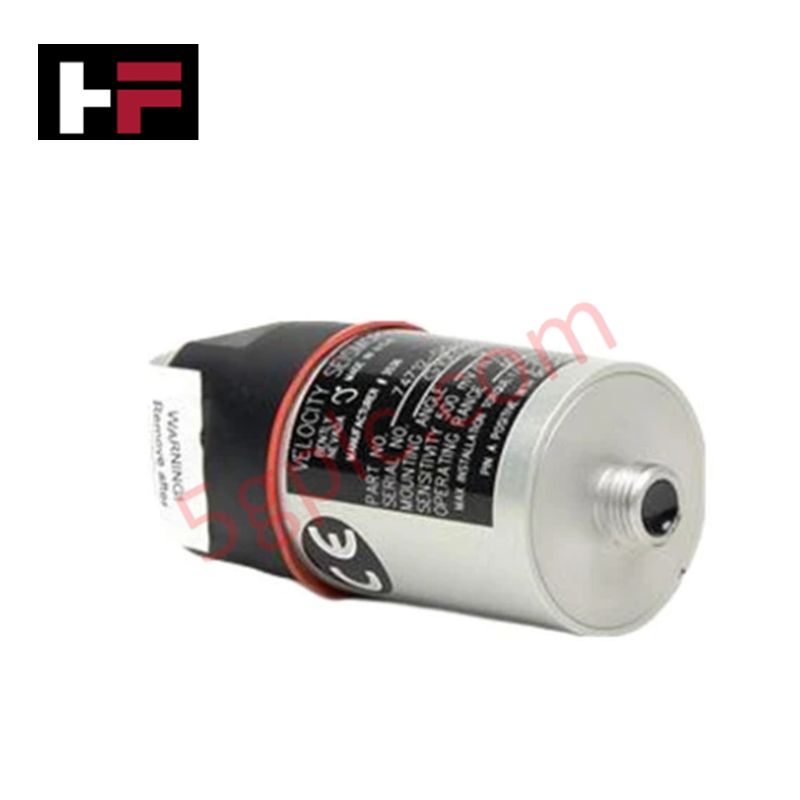
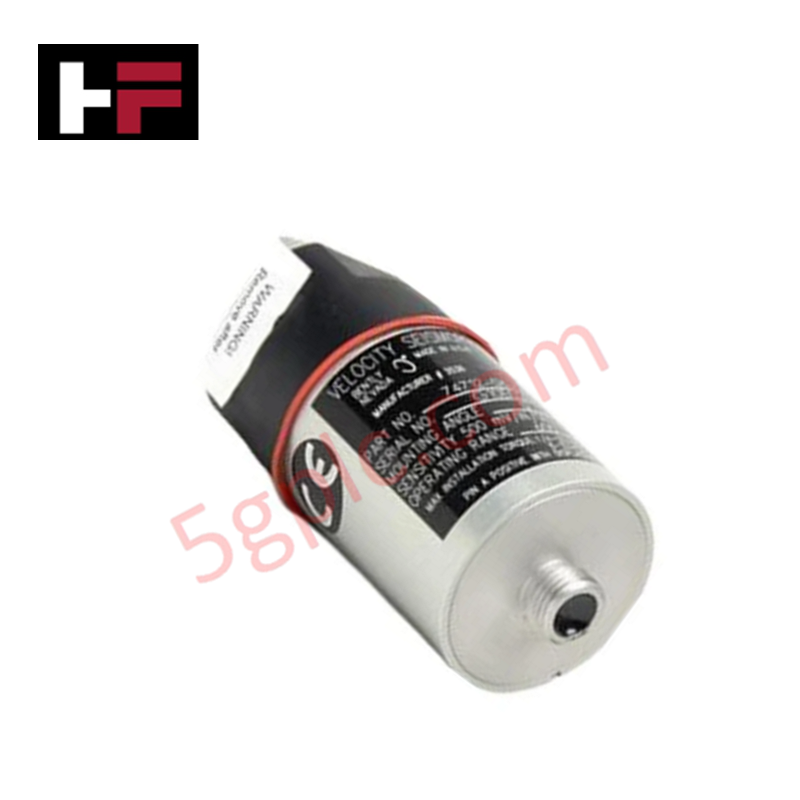
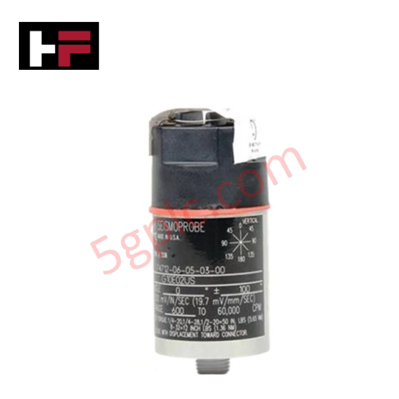
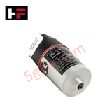
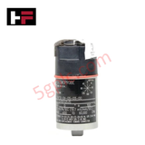
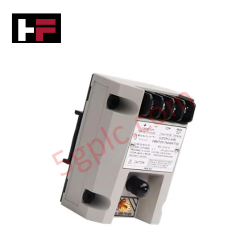
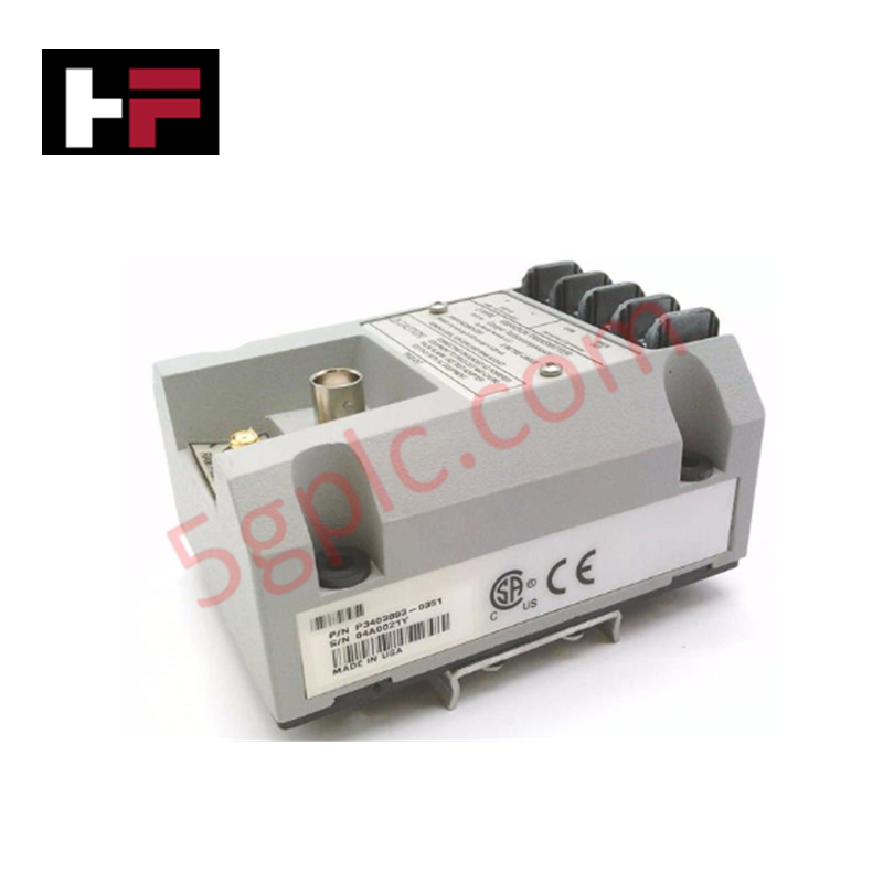
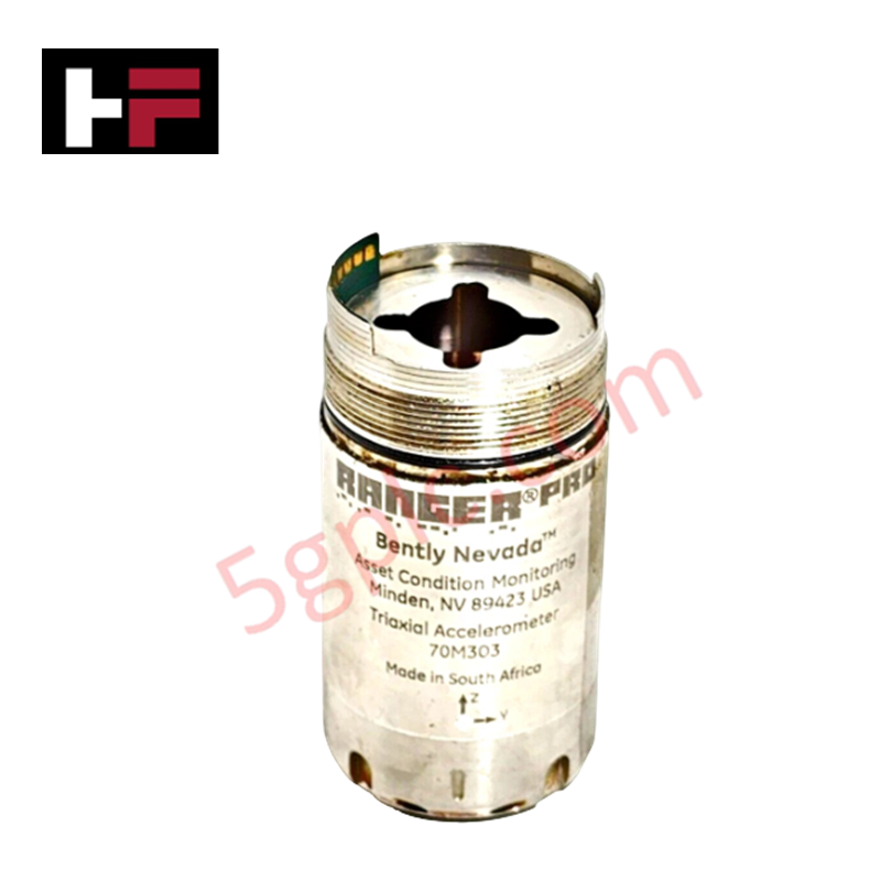
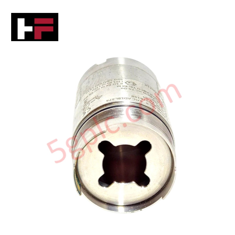
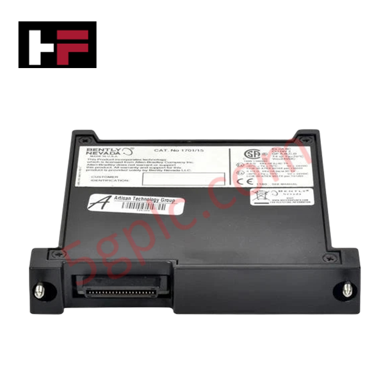
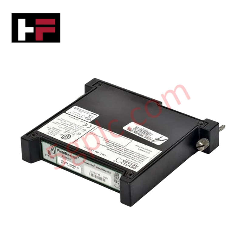
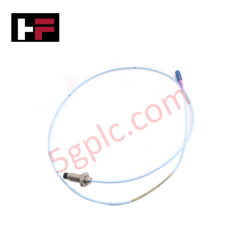
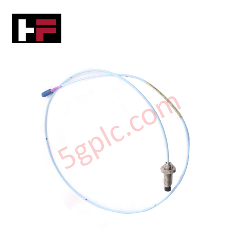
The Bently Nevada 74712-06-03-03-00, also cataloged as the 74712 Velocity Seismoprobe Transducer, operates as a dedicated hardware component for absolute casing vibration measurement within Bently Nevada Machinery Monitoring Systems.
Suffix Breakdown & Model Matrix
| Option Field | Code | Configuration Detail |
|---|---|---|
| Mounting Angle / Min Frequency | 06 | 0 deg +/- 100 deg orientation, 10 Hz (600 cpm) minimum frequency |
| Mounting Base Option | 03 | 1/2-20 UNF mounting base thread |
| Connector Option | 03 | Top-mounted terminal block connection |
| Agency Approval Option | 00 | No hazardous area approvals |
Hardware Specifications
| Parameter | Specification |
|---|---|
| Model | 74712-06-03-03-00 |
| Brand | Bently Nevada |
| Origin | USA |
| Weight | 0.48 kg |
| Dimensions | 41 mm (1.6 in) diameter typical |
| Operating Temp | High-temperature two-wire transducer rating |
| Power Consumption | Self-generating moving-coil velocity transducer |
| Transducer Type | Two-wire high-temperature velocity seismoprobe |
| Frequency Response | Minimum operating frequency 10 Hz (600 cpm) |
| Mounting Angle | 0 deg +/- 100 deg |
Rotor Dynamics and Casing Signal Execution
The 74712-06-03-03-00 moving-coil assembly generates a continuous voltage output proportional to absolute casing vibration velocity along the installation axis. Operating as a self-generating electromechanical transducer, it provides absolute velocity signals required for full-spectrum rotor dynamics assessment and structural bearing housing analysis. Solid mechanical coupling via the 1/2-20 UNF threaded base preserves linear velocity response and prevents high-frequency signal attenuation, maintaining cross-talk suppression and noise rejection across long cable runs.
Frequently Asked Questions
Q: Does the 74712-06-03-03-00 require an external power supply?
A: No, the moving-coil electrodynamic mechanism is entirely self-generating, producing a proportional AC voltage output directly at the top terminal block.
Q: How does the 03 mounting base option differ from stud-only configurations?
A: Option 03 includes an integrated 1/2-20 UNF threaded mounting base for direct mechanical coupling into tapped casing bosses.
Field Installation Guidelines
- Ensure the mounting spot on the machine casing is spot-faced flat and free of paint, scale, or debris.
- Apply a light film of oil or coupling compound to the mounting interface to optimize high-frequency signal transfer.
- Thread the 1/2-20 UNF mounting base into the tapped hole and torque to standard engineering limits using the hex flats.
- Secure two-conductor shielded signal wiring to the top terminal block using ring terminals to prevent wire fatigue under vibration.
- Ground the cable shield at the monitoring system chassis ground terminal only, ensuring the shield remains isolated at the transducer end to avoid ground loops.
Additional Information
- 100% Genuine Parts: All products are original and authentic, ensuring reliable industrial performance.
- 30-Day Refund Guarantee: Return any in-stock item within 30 days in original, unopened packaging for a full refund (excluding shipping and fees).
- 12-Month Warranty: Covers defects in materials or workmanship; excludes misuse, normal wear, or unauthorized modifications.
- Worldwide Shipping: We ship via USPS, UPS, FedEx, and DHL. Delivery times vary by country and may be subject to customs or import fees.
- Support & Contact: Technical and warranty assistance is available anytime. Contact us here: Contact.
- Purchase Guidance: Check product specifications and compatibility carefully before ordering to ensure proper application.


Tech & Buying Guide

Mastering Wire Identification in Industrial Automation: The Power of Ferrules and Cross-Ferruling
Proper wire labeling forms the cornerstone of reliable control system installation and long-term maintenance. In complex industrial automation environments, technicians terminate thousands of conductor ends inside control panels, marshalling racks, and field junction boxes. Ferrules serve as individual tube-shaped sleeve markers slipped onto conductors before final termination. While technicians historically relied on pre-printed individual letter rings, modern control panel builders utilize automated ferrule printing machines. These thermal-transfer printers generate durable, single-sleeve heat-shrink tags directly matching approved wiring schematics, significantly accelerating cabinet assembly workflows.

Understanding Marshalling Cabinets in Industrial Automation and Control Systems
Marshalling cabinets serve as the crucial connection hub between field instruments and centralized processing units. In large DCS and PLC control system architectures, hundreds of multipair field cables run from local junction boxes to the central instrument equipment room. The marshalling cabinet houses field terminal blocks, surge arresters, intrinsic safety isolation barriers, and interposing relays. By segregating field field-wiring terminations from sensitive processor hardware, engineers protect expensive controller backplanes from high-voltage transients. Consequently, this modular separation dramatically streamlines maintenance workflows and simplifies system expansion.

Essential Best Practices for PLC Wiring and Installation in Industrial Automation
Successful control system deployment begins with thoroughly reviewing manufacturer technical documentation. Controllers from major brands like Allen-Bradley, Siemens, and Schneider Electric feature unique terminal layouts. Engineers must verify voltage requirements before connecting power cables to prevent catastrophic equipment damage. Standard line connections require strict adherence to regional electrical codes and proper wire color coding. Furthermore, panel builders should always establish a robust low-impedance ground connection using at least 16-AWG copper conductor tied directly to the main plant grounding grid.