












Product Details
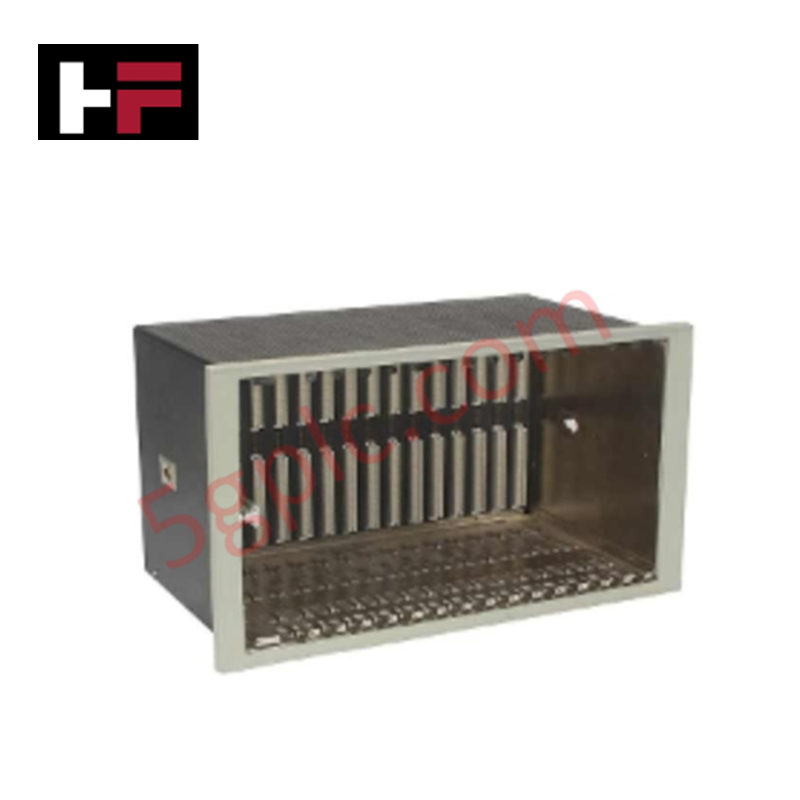
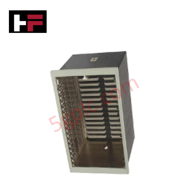
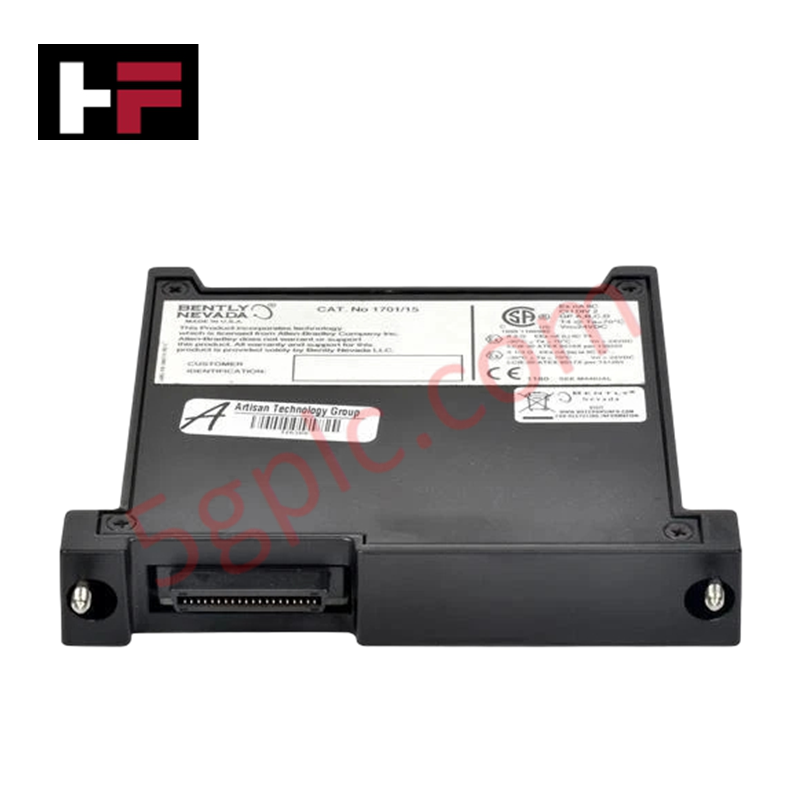
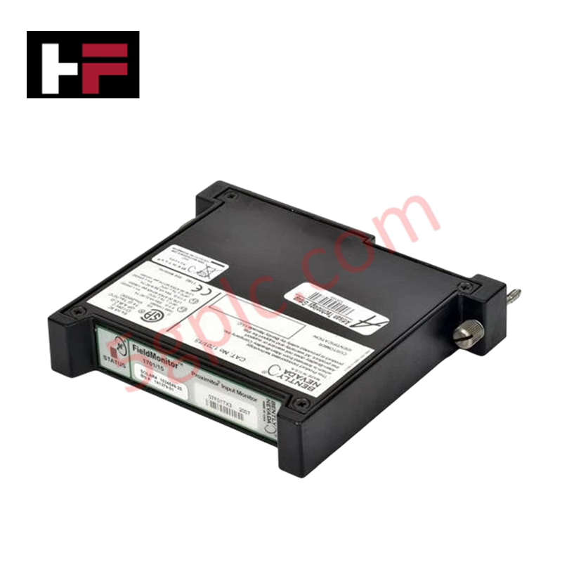
The Bently Nevada 3500/05-01-01-00-00-00, also cataloged as the 3500/05 System Rack, operates as a dedicated hardware component for physical module mounting and backplane bus signal routing within 3500 Series Machinery Protection System platforms.
Suffix Breakdown & Model Matrix
| Option Field | Code | Configuration Detail |
|---|---|---|
| Rack Size | 01 | 19-inch rack mount (16 slots) |
| Mounting Options | 01 | 19-inch EIA rack mounting format |
| Agency Approval Option | 00 | None / Standard non-certified configuration |
| Reserved Option 1 | 00 | Unassigned / Standard default |
| Reserved Option 2 | 00 | Unassigned / Standard default |
Hardware Specifications
| Parameter | Specification |
|---|---|
| Model | 3500/05-01-01-00-00-00 |
| Brand | Bently Nevada |
| Origin | USA |
| Weight | 4.54 kg (10.00 lbs) |
| Dimensions | Standard 19-inch EIA rack width, 16-slot capacity |
| Operating Temp | -30 deg C to +65 deg C (-22 deg F to +149 deg F) |
| Power Consumption | Passive chassis backplane structure |
| Bus Architecture | High-speed internal backplane communications bus |
| Slot Density | 16 module slots (Slot 0 reserved for Power Supply, Slot 1 for RIM) |
Rotor Dynamics and Cross-Talk Suppression
The 3500/05 16-slot chassis provides high-density backplane signal pathways that route raw eddy-current probe voltage and dynamic vibration waveforms directly between monitor modules and keyphasor inputs. Integrated shielding plane geometry inside the multilayer backplane printed circuit board maintains cross-talk suppression between adjacent high-frequency dynamic channels. This signal integrity enables accurate rotor dynamics monitoring and gap voltage validation across full-scale machine monitoring operations.
Frequently Asked Questions
Q: Can modules be inserted or removed from the 3500/05 backplane while power is applied?
A: Yes, modules designed for the 3500 Series system support hot-swapping within the 3500/05 rack without interrupting operation of unaffected slots or causing backplane signal corruption.
Q: How is chassis grounding managed across the 16 slots of the 3500/05 chassis?
A: The rack frame features a central earth ground bonding stud on the rear enclosure to maintain equipotential reference across all installed card guides and signal shields.
Field Installation Guidelines
- Mount the 19-inch 3500/05 chassis into a standard EIA instrument rack using appropriate panel mounting hardware.
- Connect a dedicated heavy-gauge grounding conductor from the chassis earth ground stud on the rear of the rack to the main station ground bar.
- Ensure slot 0 is populated with a 3500 Power Supply module and slot 1 contains the Rack Interface Module (RIM) before installing monitoring cards.
- Insert monitor modules along card guides until the backplane connectors seat completely, then tighten upper and lower front-panel thumbscrews.
- Route dynamic signal wires away from high-voltage field wiring to prevent electromagnetic interference coupling into the backplane.
Additional Information
- 100% Genuine Parts: All products are original and authentic, ensuring reliable industrial performance.
- 30-Day Refund Guarantee: Return any in-stock item within 30 days in original, unopened packaging for a full refund (excluding shipping and fees).
- 12-Month Warranty: Covers defects in materials or workmanship; excludes misuse, normal wear, or unauthorized modifications.
- Worldwide Shipping: We ship via USPS, UPS, FedEx, and DHL. Delivery times vary by country and may be subject to customs or import fees.
- Support & Contact: Technical and warranty assistance is available anytime. Contact us here: Contact.
- Purchase Guidance: Check product specifications and compatibility carefully before ordering to ensure proper application.


Tech & Buying Guide
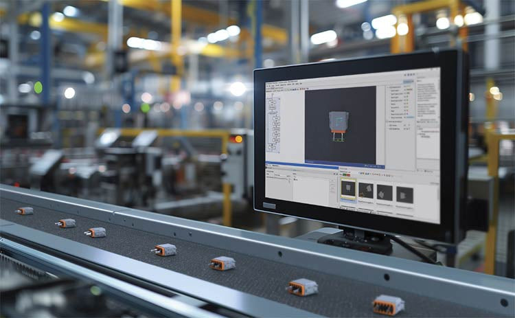
Modern Industrial Automation: Transforming Safety and Efficiency in Mining Operations
Industrial automation has evolved from a simple manufacturing tool into the operational backbone of high-risk sectors. Modern mining operations increasingly rely on advanced control systems, programmable logic controllers (PLCs), distributed control systems (DCS), and artificial intelligence to address deep-underground hazards. By replacing manual labor in high-risk zones, factory automation technologies protect personnel while significantly boosting operational throughput.

Step-by-Step System Cabinet Health Check Guide for PLC and DCS Infrastructure
