










Product Details
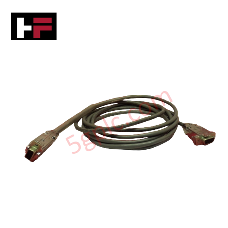
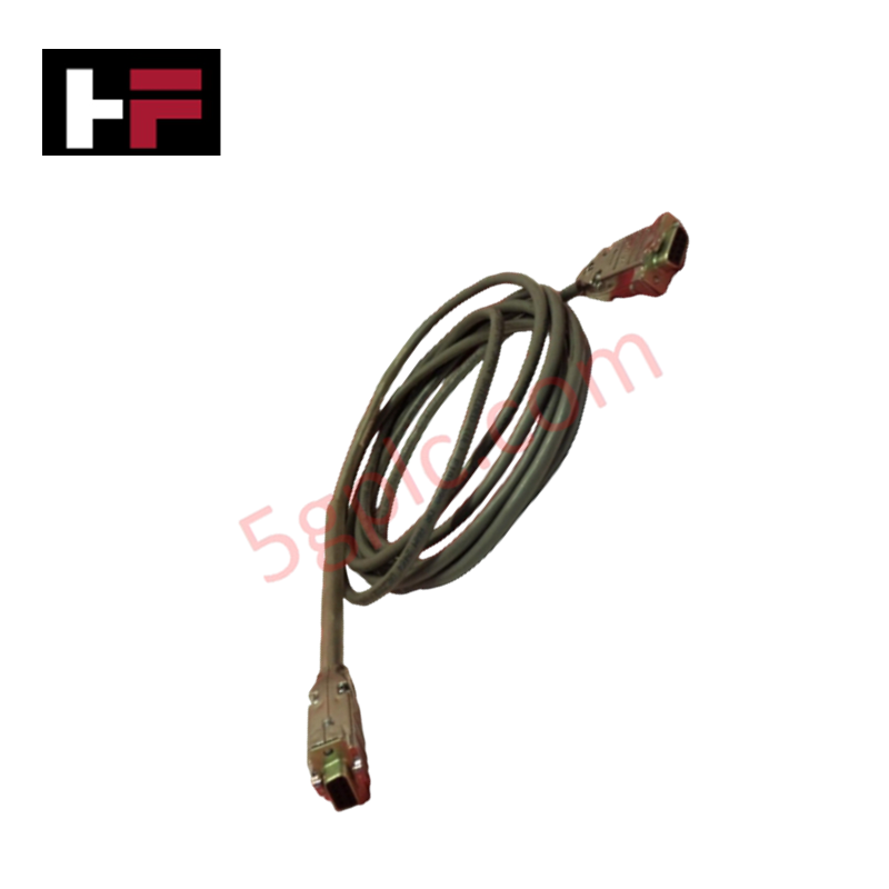
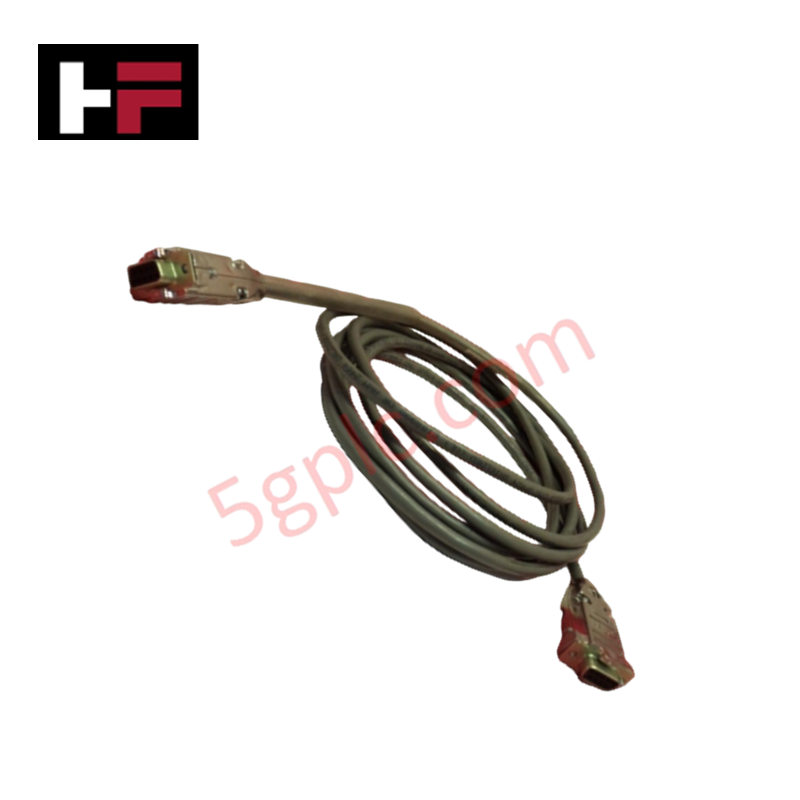
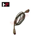
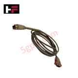
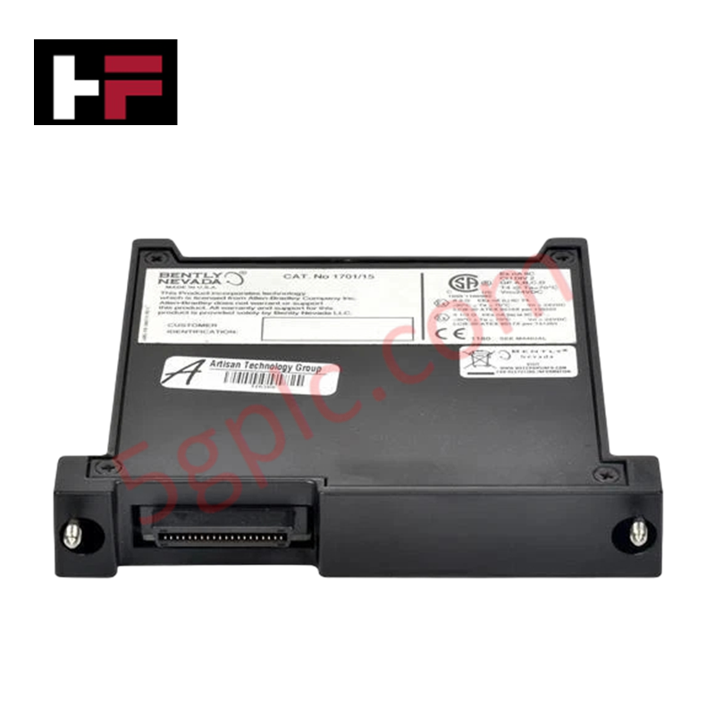
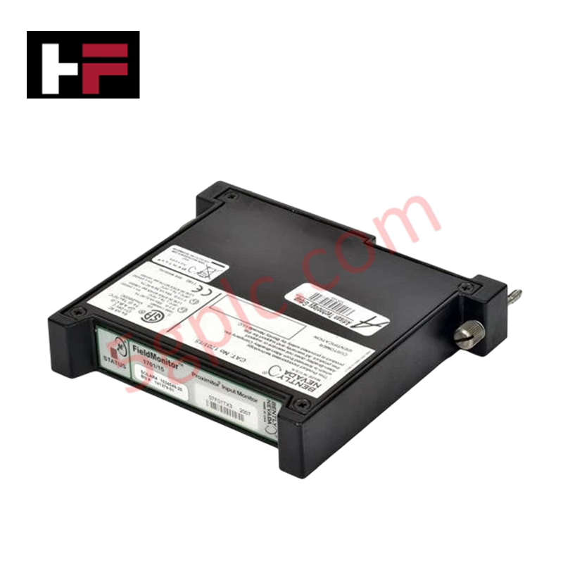
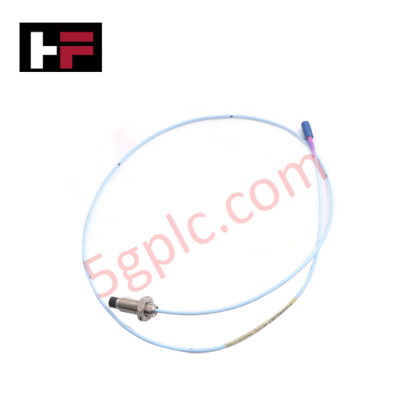
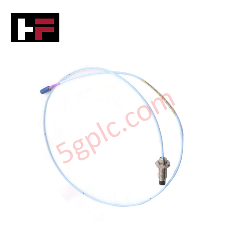
Configured for rack connections and transducer signal routing in 3500 System networks, the Bently Nevada 130118-0010-02 (130118 PLC Cable) provides direct physical/electrical execution.
Suffix Breakdown & Model Matrix
| Option Field | Code | Configuration Detail |
|---|---|---|
| Length Option | 0010 | 10-foot total cable assembly length |
| Interface / Assembly Option | 02 | 2-pin MIL-C-5015 style connector interface |
Hardware Specifications
| Parameter | Specification |
|---|---|
| Model | 130118-0010-02 |
| Brand | Bently Nevada |
| Origin | USA |
| Weight | 0.40 lbs (0.18 kg) |
| Dimensions | 38.1 mm x 19.1 mm x 25.4 mm (connector housing profile) |
| Operating Temp | -50 deg C to +120 deg C (-58 deg F to +248 deg F) |
| Power Consumption | Passive signal conductor assembly (18 to 30 VDC powered loop supported) |
| Cable Length | 10 feet |
| Frequency Range | 2 Hz to 10 kHz (+3 dB) |
| Measurement Range | Up to 50 g peak (490 m/s2) |
| Nominal Sensitivity | 100 mV/g |
| Connector Type | 2-pin MIL-C-5015 style connector |
Signal Preservation and Cross-Talk Suppression in Machinery Protection
The 130118-0010-02 assembly routes low-level dynamic vibration signals between field sensors and 3500 series rack monitoring modules. Standardized conductor geometry and internal twisted-pair shielding optimize dynamic signal integrity over its 10-foot length. Maintaining steady impedance properties across the 2 Hz to 10 kHz frequency spectrum prevents signal attenuation and supports cross-talk suppression between neighboring monitoring channels during high-amplitude transient events.
Frequently Asked Questions
Q: Does the 130118-0010-02 cable require external power to operate?
A: No, the cable assembly is a passive conductor harness designed to carry dynamic 100 mV/g sensor signals and loop power supplied by connected 18 to 30 VDC monitor channels.
Q: What connector interface is integrated into the 130118-0010-02 cable assembly?
A: The assembly incorporates a 2-pin MIL-C-5015 style connector engineered for secure coupling to field transducer terminals.
Field Installation Guidelines
- Inspect the 2-pin MIL-C-5015 connector pins and outer cable jacketing for mechanical defects prior to field installation.
- Maintain a minimum bend radius of six times the cable outer diameter during tray layout to prevent conductor strain.
- Align the MIL-C-5015 keyway with the mating transducer receptacle and hand-tighten the threaded coupling ring until fully seated.
- Route the cable through grounded protective conduit, ensuring complete isolation from high-voltage motor power lines.
- Connect the cable shield drain wire to the designated system rack chassis ground terminal to prevent ground loops.
Additional Information
- 100% Genuine Parts: All products are original and authentic, ensuring reliable industrial performance.
- 30-Day Refund Guarantee: Return any in-stock item within 30 days in original, unopened packaging for a full refund (excluding shipping and fees).
- 12-Month Warranty: Covers defects in materials or workmanship; excludes misuse, normal wear, or unauthorized modifications.
- Worldwide Shipping: We ship via USPS, UPS, FedEx, and DHL. Delivery times vary by country and may be subject to customs or import fees.
- Support & Contact: Technical and warranty assistance is available anytime. Contact us here: Contact.
- Purchase Guidance: Check product specifications and compatibility carefully before ordering to ensure proper application.


Tech & Buying Guide

Step-by-Step System Cabinet Health Check Guide for PLC and DCS Infrastructure

Top 5 Operational Advantages of HMIs in Modern Factory Automation
