










Product Details
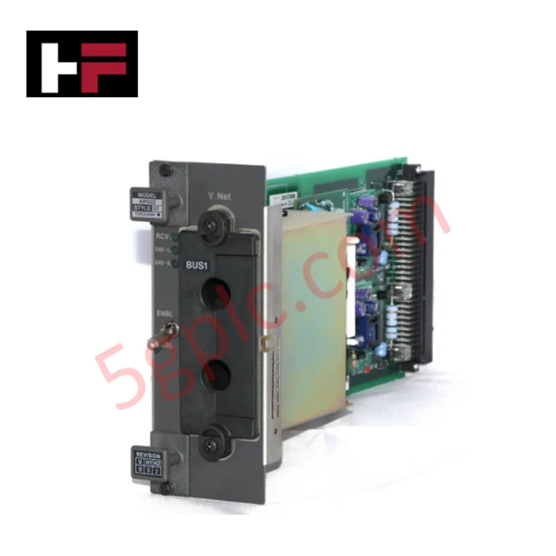
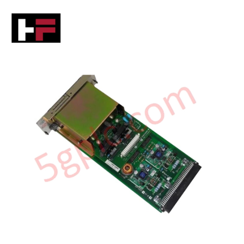
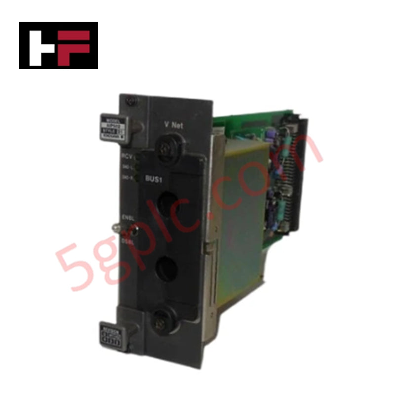
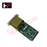
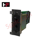
Configured for signal coupling and bus interface execution in Yokogawa Centum CS and Centum VP platforms, the Yokogawa AIP502 S1 (AIP502 V-Net Coupler Module) provides direct physical/electrical execution. It serves as an interface node within the proprietary V-Net communications topology to link sub-rack control units while preserving signal waveform fidelity.
Suffix Breakdown & Model Matrix
| Code / Option | Description |
|---|---|
| Model: AIP502 | V-Net Coupler Module Base Designation |
| S1 | Hardware Style Revision 1 |
Hardware Specifications
| Parameter | Specification |
|---|---|
| Model | AIP502 S1 |
| Brand | Yokogawa |
| Origin | Japan |
| Weight | 0.6 kg (1 lbs 5.0 oz) |
| Dimensions | 15.2 cm x 7.6 cm x 25.4 cm (6.0 in x 3.0 in x 10.0 in) |
| Operating Temp | 0 to +50 deg C |
| Power Consumption | Sub-rack backplane powered |
| Compatibility | Yokogawa Centum CS / Centum VP |
| Function | V-Net Signal Coupling |
| Network Type | V-Net Bus Interface |
Channel-to-Channel Isolation and Loop Protocol Integration
The AIP502 S1 provides channel-to-channel isolation across internal V-Net bus coupling paths to prevent ground potential differences between interconnected sub-racks. While low-level field devices communicate using 4-20 mA HART loop protocol architectures down at the process layer, the AIP502 S1 operates at the high-speed system network level, isolating backplane data lines from common-mode electrical noise and high-frequency transient interference.
Frequently Asked Questions
Q: What is the primary function of the AIP502 S1 in a Centum VP system?
A: The module acts as a hardware coupler for V-Net communications, transmitting data frames between backplane buses and main system network cables.
Q: Can the AIP502 S1 be inserted into a backplane sub-rack while power is applied?
A: Hot-swapping must strictly adhere to Yokogawa Centum system guidelines; power isolation or redundant pair configuration is recommended to avoid transient bus errors during physical module replacement.
Field Installation Guidelines
- ESD Protection: Wear a properly grounded anti-static wrist strap during handling to prevent electrostatic damage to internal coupling transformers and IC components.
- Module Insertion: Align card guides with the target sub-rack slot and push firmly until rear multi-pin connectors are fully seated into the backplane chassis.
- Shield Grounding: Connect all incoming coaxial or shielded network cable braids directly to the cabinet earthing bus bar using short, low-impedance ground straps.
- Cable Separation: Route V-Net communication cables in isolated wire trays separated from AC power distribution lines and high-current motor cables.
Additional Information
- 100% Genuine Parts: All products are original and authentic, ensuring reliable industrial performance.
- 30-Day Refund Guarantee: Return any in-stock item within 30 days in original, unopened packaging for a full refund (excluding shipping and fees).
- 12-Month Warranty: Covers defects in materials or workmanship; excludes misuse, normal wear, or unauthorized modifications.
- Worldwide Shipping: We ship via USPS, UPS, FedEx, and DHL. Delivery times vary by country and may be subject to customs or import fees.
- Support & Contact: Technical and warranty assistance is available anytime. Contact us here: Contact.
- Purchase Guidance: Check product specifications and compatibility carefully before ordering to ensure proper application.


Tech & Buying Guide

Understanding Siemens PLC Memory Cards: MMC, SMC, and SD Solutions in Industrial Automation
Memory management plays a pivotal role in maintaining control system reliability across modern manufacturing plants. Industrial control systems rely on specialized memory cards to store project logic, firmware updates, and retentive system data. Siemens uses several memory architectures, including Micro Memory Cards (MMC) and SIMATIC Memory Cards (SMC). Engineers must understand these hardware variations to ensure zero data loss and minimize downtime during maintenance routines.

Redefining Control Systems: The Rise of Flexible I/O Modules in Industrial Automation
Conventional input-output architectures often limit engineering agility and inflate long-term inventory costs. Today, Flexible Input/Output Modules (FIOM) are transforming how control system engineers design, commission, and maintain automation infrastructure. By allowing individual channel software configuration, FIOM technology bridges the gap between rigid hardware design and dynamic plant requirements.
Understanding Modern SCADA Systems: Architecture, Communication Topologies, and Industrial Applications
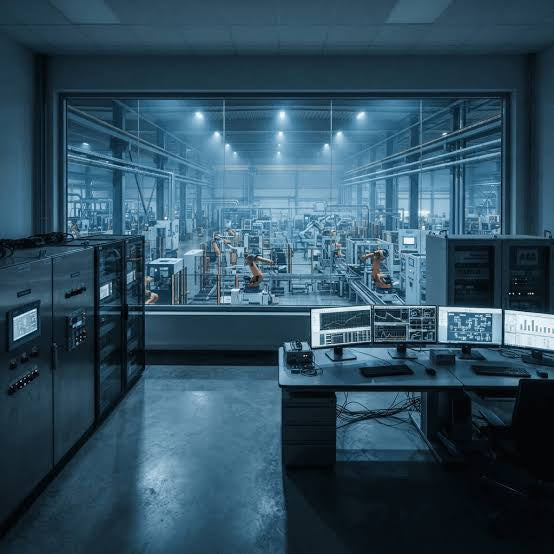
Supervisory Control and Data Acquisition (SCADA) systems form the digital backbone of modern industrial automation. They collect critical field data, transmit signals across vast distances, and empower plant operators with real-time process visibility. Across modern infrastructures, SCADA solutions streamline centralized control and maintain continuous operational uptime.