










Product Details
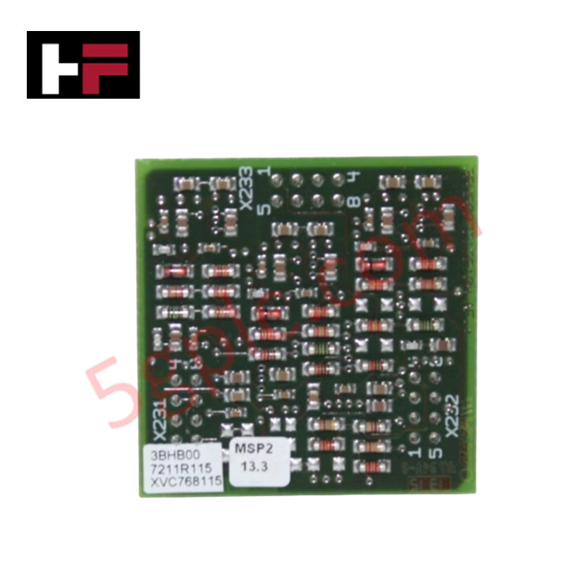
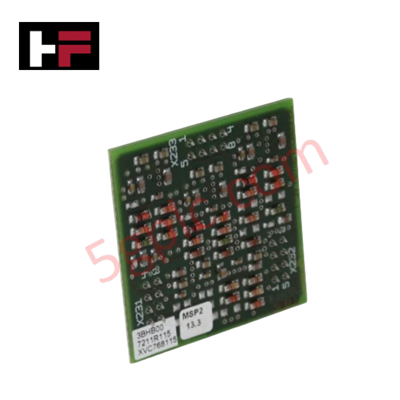
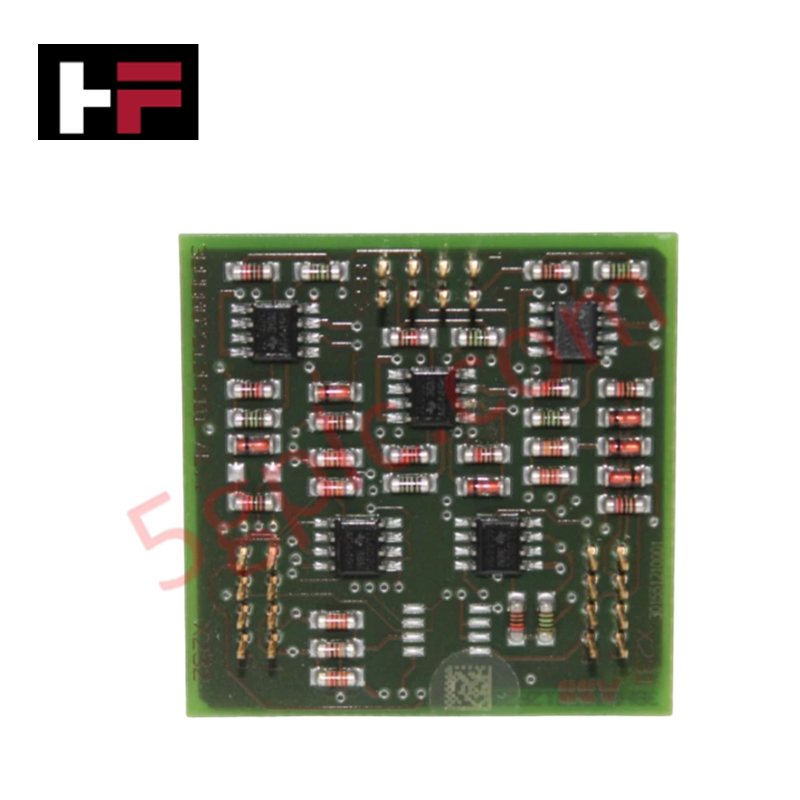
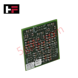
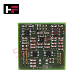
The ABB XVC768115 3BHB007211R115, also cataloged as the XVC768115 Pulse Output Module, operates as a dedicated hardware component for digital pulse signal generation within controller backplanes and drive networks. Configured for high-speed transmission, the hardware translates internal logic states into discrete pulse trains up to a maximum frequency of 1 kHz. It routes these localized electrical transitions through an isolated output stage, providing direct physical interface execution to peripheral counter inputs or slave tracking nodes.
Hardware Specifications
| Parameter | Specification |
|---|---|
| Model | XVC768115 3BHB007211R115 |
| Brand | ABB |
| Origin | Switzerland |
| Weight | 0.40 kg |
| Dimensions | Standard Chassis Panel Mount Footprint |
| Operating Temp | -10 to +60 deg C |
| Power Consumption | 6 W |
| Rated Supply Voltage | 24 V DC (+/-10%) |
| Output Signal Type | Digital pulse output |
| Maximum Pulse Frequency | Up to 1 kHz |
| Typical Response Time | < 5 ms |
| Electrical Isolation | Functional isolation between control electronics and output stage |
| Storage Temperature Range | -25 to +70 deg C |
| Protection Class | IP20 |
| Mounting Method | Surface or panel mounting |
Profinet / EtherNet/IP Deterministic Networks and I/O Density Scaling
The internal microcontroller matches pulse execution cycles with network synchronization schedules. When this pulse output module is operated across Profinet / EtherNet/IP deterministic networks, precise timing alignment is mandatory to maintain the < 5 ms response envelope without signal drift. In applications demanding rapid I/O density scaling, any mismatch in backplane bus velocity or task cycle timing can introduce clock jitter, destabilizing the 1 kHz frequency consistency across simultaneous active channels.
Frequently Asked Questions
Q: What are the specific hot-swap limits for the XVC768115 module under 24 V DC load conditions?
A: This module does not support live insertion or hot-swapping while the 24 V DC supply lines or the output stage loops are energized. Power isolation must be fully verified before removing the assembly to prevent transient arc generation and damage to the internal logic components.
Q: How does a fluctuation in the 24 V DC supply voltage affect the 1 kHz pulse output execution?
A: The module maintains normal operation within a +/-10% envelope of the 24 V DC supply. Voltage deviations exceeding these thresholds will destabilize the functional isolation thresholds and can cause intermittent switching errors or response latencies greater than 5 ms.
Q: What are the restrictions regarding the maximum cable length attached to the pulse output stage?
A: Cable lengths are bounded by line capacitance limits to prevent attenuation of the 1 kHz square wave. Long, unshielded wire paths will degrade the pulse edge definition, causing connected PLC or counter inputs to miss edge registration cycles.
Field Installation Guidelines
Mount the IP20-rated enclosure vertically using the designated surface or panel mounting points within a protected, clean automation cabinet. Ground the metallic backplane frame directly to the primary copper station earth bus utilizing a low-impedance conductor to maximize functional isolation efficiency. Route the digital pulse output lines inside separate, shielded wire channels segregated from high-voltage AC motor lines to eliminate inductive cross-talk and preserve signal edges. Ensure that air ventilation openings remain unblocked to prevent thermal accumulation beyond the certified -10 to +60 deg C operating temperature spectrum.
Additional Information
- 100% Genuine Parts: All products are original and authentic, ensuring reliable industrial performance.
- 30-Day Refund Guarantee: Return any in-stock item within 30 days in original, unopened packaging for a full refund (excluding shipping and fees).
- 12-Month Warranty: Covers defects in materials or workmanship; excludes misuse, normal wear, or unauthorized modifications.
- Worldwide Shipping: We ship via USPS, UPS, FedEx, and DHL. Delivery times vary by country and may be subject to customs or import fees.
- Support & Contact: Technical and warranty assistance is available anytime. Contact us here: Contact.
- Purchase Guidance: Check product specifications and compatibility carefully before ordering to ensure proper application.









Tech & Buying Guide

Mastering the Siemens PLC Scan Cycle: How the CPU Executes Automation Programs
Industrial automation relies heavily on programmable logic controllers (PLCs) to manage complex manufacturing processes. Many engineers dive straight into programming without mastering the underlying architecture. However, understanding how a PLC CPU executes a program ensures reliable system design. Therefore, mastering the scan cycle optimizes both performance and troubleshooting in modern control systems.

How to Connect to Siemens S7 PLCs: 5 Essential Communication Methods
Establishing a reliable hardware link between a programming terminal and a Siemens SIMATIC controller is essential for engineering workflows. Field engineers rely on distinct physical layers, ranging from legacy serial connections to high-speed Industrial Ethernet protocols. Modern factory automation environments prioritize fast data transfer and seamless driver integration. Selecting the correct connection method simplifies program downloads, online monitoring, and system troubleshooting in complex control systems.

Will PLCs Become Obsolete? The Future of Control Systems in Industry 4.0
Modern manufacturing is undergoing a rapid technological transformation driven by Industry 4.0 innovations. Technologies like Artificial Intelligence (AI), Machine Learning (ML), and the Industrial Internet of Things (IIoT) are dominating discussions across the factory automation sector. Consequently, many engineers wonder if these advanced digital tools will eventually replace traditional Programmable Logic Controllers (PLCs). However, evaluating the core physics of industrial operations reveals a very different reality for control systems.