








Product Details
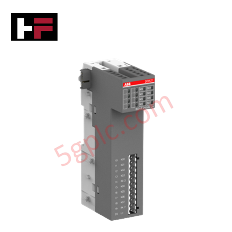
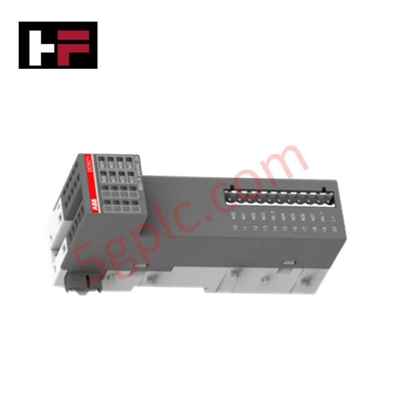
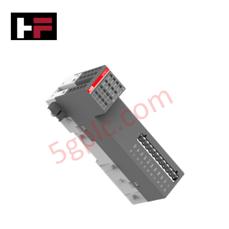
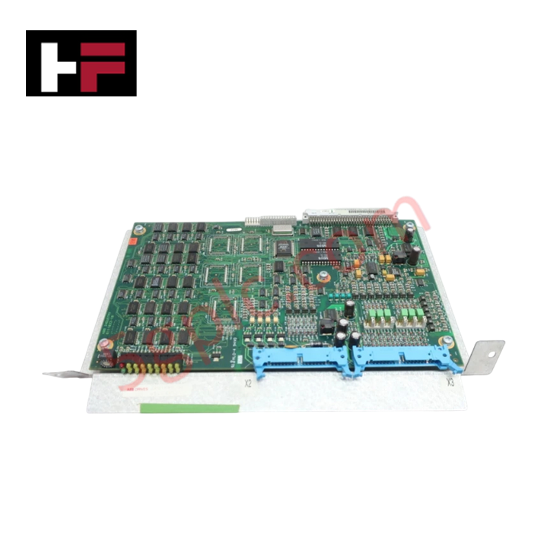
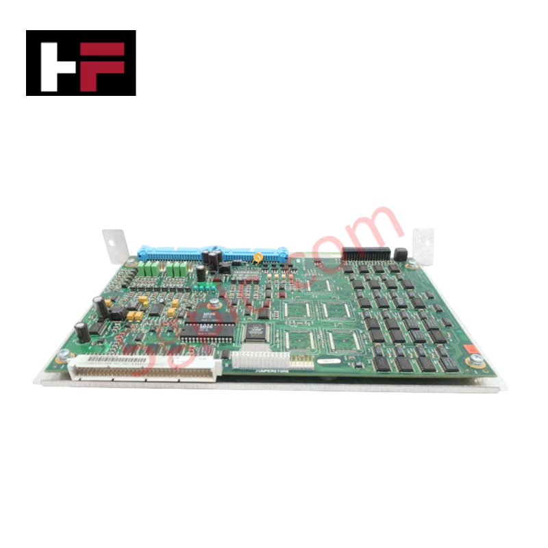
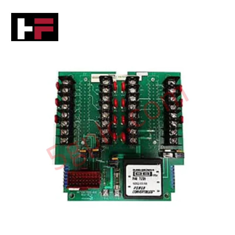
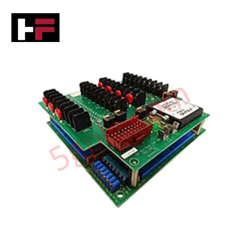
The ABB DO571 1TNE968902R2202, also cataloged as the DO571 Digital Output Module, operates as a dedicated hardware component for discrete state manipulation within Distributed Automation I/Os networks. Configured for switching physical isolation loops, the hardware routes up to 8 relay outputs operating over mixed electrical potentials. It handles cyclic load processing between host automation logic configurations and external execution points, maintaining a galvanic threshold via integrated structural relays under an explicit internal voltage source.
Hardware Specifications
| Parameter | Specification |
|---|---|
| Model | DO571 1TNE968902R2202 |
| Brand | ABB |
| Origin | Germany |
| Weight | 0.138 kg |
| Dimensions | 135 mm x 74 mm x 34 mm |
| Operating Temp | 0 to +60 deg C |
| Power Consumption | 4.5 W |
| Number of Digital Outputs | 8 |
| Output Type | Relay |
| Output Voltage Type | AC / DC |
| Output Voltage Range | 24 to 230 V |
| Output Voltage Maximum | 195.5 to 276 V |
| Output Current | 2 A per channel |
| Connection Type | Pluggable |
| Degree of Protection | IP20 |
| Supply Voltage | 20.4 to 28.8 V DC |
| Storage Temperature | -40 to +70 deg C |
Backplane Bus Communication Velocity Licences and I/O Density Scaling
The internal logic card architecture maps the 8 mechanical contact arrays to independent bit registers within the host PLC chassis. When configuring extensive local nodes demanding high-speed synchronization, system engineering must match module placement profiles with active backplane bus communication velocity licences to maintain fixed scan cycle integrity. This optimization allows flexible I/O density scaling across adjacent eCo-series frames without introducing tracking register propagation delays or disrupting deterministic processing schedules during high-frequency relay state transitions.
Frequently Asked Questions
Q: What are the physical constraints and electrical hazards of hot-swapping the DO571 module?
A: This module does not support live hot-swapping functionality. The primary 20.4 to 28.8 V DC supply lines and all external loop loads up to 240 V AC must be fully isolated before extracting the pluggable terminal blocks to prevent contact arcing, logic errors, or permanent circuit board component degradation.
Q: How does the module react if the external switching voltage reaches the maximum 276 V limit?
A: The module accommodates transient peaks up to 276 V across the open relay poles. Continuous exposure to voltages above this threshold compromises internal trace insulation paths and can induce premature contact welding or dielectric degradation across adjacent channels.
Q: Are the 8 relay channels sharing a single common line or are they isolated from each other?
A: The technical matrix demands referencing the wiring diagrams for grouped commons. Exceeding the combined 2 A current distribution limit per block can trace thermal faults onto the pluggable connection interface.
Field Installation Guidelines
Mount the 0.138 kg assembly onto a standard symmetrical DIN rail secured within an IP20-rated, ventilated industrial panel structure. Ensure that the DIN rail framework is directly bonded to the primary station copper earth bar using a low-impedance connection path to mitigate noise induction. Route all high-voltage inductive output lines (up to 240 V AC) through distinct wireways separated from low-voltage DC communication bus cables to suppress magnetic cross-talk. Maintain standard air spacing above and below the 135 mm x 74 mm x 34 mm housing boundaries to facilitate heat dissipation within the bounded 0 to +60 deg C operational threshold.
Additional Information
- 100% Genuine Parts: All products are original and authentic, ensuring reliable industrial performance.
- 30-Day Refund Guarantee: Return any in-stock item within 30 days in original, unopened packaging for a full refund (excluding shipping and fees).
- 12-Month Warranty: Covers defects in materials or workmanship; excludes misuse, normal wear, or unauthorized modifications.
- Worldwide Shipping: We ship via USPS, UPS, FedEx, and DHL. Delivery times vary by country and may be subject to customs or import fees.
- Support & Contact: Technical and warranty assistance is available anytime. Contact us here: Contact.
- Purchase Guidance: Check product specifications and compatibility carefully before ordering to ensure proper application.
Tech & Buying Guide

Batch vs Continuous Processing in Industrial Automation: Architectural Strategies for Control Engineers
Selecting the proper control architecture remains a pivotal decision when designing industrial automation systems. Automation engineers must evaluate whether a batch or continuous process model best fits their production requirements. This fundamental choice influences PLC and DCS programming, hardware redundancy, sensor selection, and overall factory automation layouts.

Demystifying Signal Isolators: Operating Principles, Architectural Types, and Industrial Applications
Industrial automation systems rely on pristine analog signal transmission across complex control loops. Instrument technicians and system integrators frequently deploy signal isolators to maintain signal integrity between field sensors and control platforms. Eliminating electrical noise, ground loops, and high-voltage transients protects delicate PLC, DCS, and SCADA input channels from permanent damage.
Demystifying Industrial Control Systems: Comparing PLC, DCS, RTU, SCADA, and PAC
Modern factory automation relies on distinct control architectures to manage complex process environments efficiently. Control engineers often evaluate PLC, DCS, RTU, SCADA, and PAC platforms when designing industrial infrastructure. Understanding the functional boundaries of each technology ensures optimal system performance, high availability, and long-term cost efficiency.