


Product Details
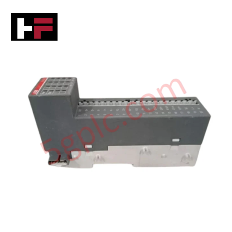
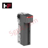
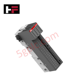
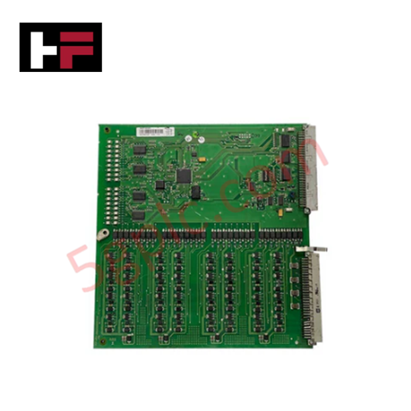
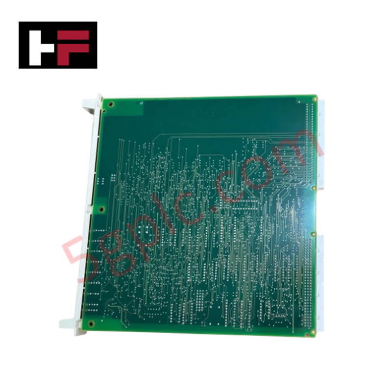
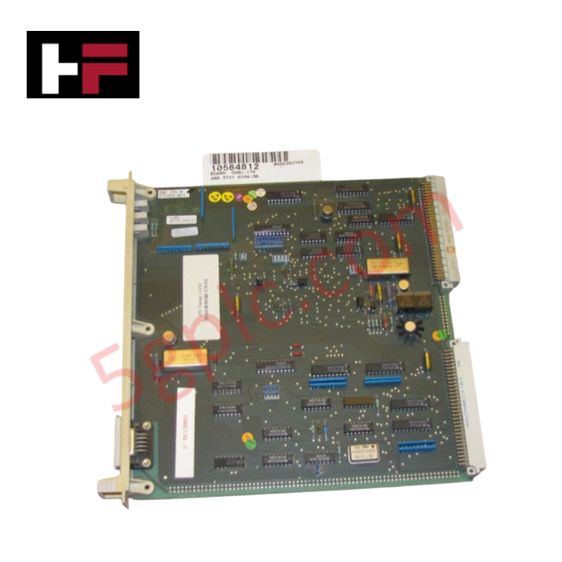
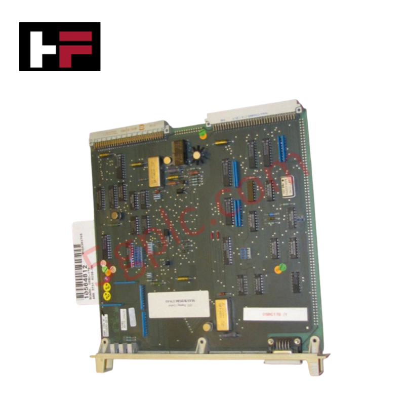
The ABB DO562 1SAP230900R0000, also cataloged as the DO562 Digital Output Module, operates as a dedicated hardware component for binary signal switching within S500-eCo Distributed Automation PLCs. Configured with 16 transistor channels arranged in a 1-wire connection typology, the hardware executes direct electrical state manipulation of field devices. It translates internal logic commands into physical DC potentials to energize local actuators, interfacing via pluggable terminals that operate under a standardized industrial voltage envelope.
Hardware Specifications
| Parameter | Specification |
|---|---|
| Model | DO562 1SAP230900R0000 |
| Brand | ABB |
| Origin | Germany |
| Weight | 0.16 kg |
| Dimensions | 75 mm x 135 mm x 34 mm |
| Operating Temp | 0 to +60 deg C |
| Power Consumption | 3 W |
| Function | 16 Digital Outputs (DO) |
| Output Type | Transistor |
| Output Voltage Type | DC |
| Output Current | 0.5 A per channel |
| Output Voltage Range | 20.4 to 28.8 V DC |
| Connection Type | Pluggable |
| Degree of Protection | IP20 |
| Supply Voltage | 20.4 to 28.8 V DC |
Backplane Bus Communication Velocity Licences and I/O Density Scaling
The module handles discrete state matrices across its 16-channel transistor block, interfacing directly with the internal backplane architecture of the PLC station. When implementing extensive local configurations, system engineers must evaluate the aggregate current draw against backplane bus communication velocity licences to prevent network latency accumulation. Proper configuration allows matching I/O density scaling across adjacent nodes, preserving predictable execution cycles without triggering backplane register timeouts during multi-channel state transitions.
Frequently Asked Questions
Q: What are the specific hot-swap limits for the DO562 module during active rack operation?
A: Live extraction or insertion of the DO562 module is restricted while the backplane bus or the 24 VDC external terminal supply is energized. Removing the pluggable interface under load can induce electrical arcing across pin contacts, leading to localized transistor degradation or logic disruptions on the controller rack.
Q: How does the module handle short-circuit faults or overcurrent conditions on an individual 0.5 A transistor output channel?
A: The transistor output stage contains embedded thermal and current limits. When an external path draws load current exceeding the 0.5 A nominal channel ceiling, the circuit restricts the current path or enters a safe shutdown mode until the fault path is isolated.
Field Installation Guidelines
Mount the 0.16 kg housing vertically onto standard DIN rail frameworks inside an IP20-compliant industrial enclosure. Verify that the primary mounting rail maintains a low-impedance ground track directly back to the main copper station grounding bar. Route all 24 VDC discrete output wire runs through dedicated, shielded panel wireways separate from high-voltage AC motor or power distribution lines to suppress external electromagnetic cross-talk. Secure all pluggable terminal blocks fully into their matching slots to prevent vibration-induced contact interruption across the 75 mm x 135 mm x 34 mm physical envelope.
Additional Information
- 100% Genuine Parts: All products are original and authentic, ensuring reliable industrial performance.
- 30-Day Refund Guarantee: Return any in-stock item within 30 days in original, unopened packaging for a full refund (excluding shipping and fees).
- 12-Month Warranty: Covers defects in materials or workmanship; excludes misuse, normal wear, or unauthorized modifications.
- Worldwide Shipping: We ship via USPS, UPS, FedEx, and DHL. Delivery times vary by country and may be subject to customs or import fees.
- Support & Contact: Technical and warranty assistance is available anytime. Contact us here: Contact.
- Purchase Guidance: Check product specifications and compatibility carefully before ordering to ensure proper application.
Tech & Buying Guide

Core Components of Programmable Logic Controllers (PLC) in Industrial Automation
A Programmable Logic Controller (PLC) serves as the digital backbone of modern factory automation. Whether you are managing complex assembly lines or simple process loops, understanding the hardware and software architecture of a PLC is essential for any control systems engineer.

PLC vs. PC: Navigating the Architectural Differences in Industrial Automation
In the realm of factory automation, professionals often debate the roles of Programmable Logic Controllers (PLCs) and Personal Computers (PCs). While both devices share fundamental computing architectures—including a processor, memory, and an operating system—their design philosophies diverge significantly. Understanding these distinctions is critical for selecting the right hardware for your industrial control systems.

Essential SCADA Features for Modern IoT-Enabled Industrial Automation
The convergence of traditional SCADA systems with the Industrial Internet of Things (IIoT) has redefined factory automation. Choosing a robust platform requires more than just standard monitoring capabilities. In this era of Industry 4.0, your supervisory system must bridge the gap between legacy control systems and enterprise-level data integration.