


Product Details
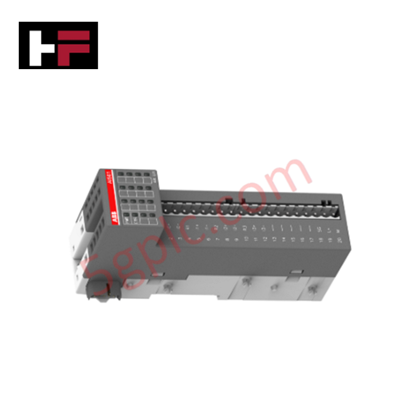
The ABB AI561 1TNE968902R1101, also cataloged as the AI561 Analog Input Module, operates as a dedicated hardware component for multi-channel analog signal acquisition within S500-eCo distributed I/O systems. The module maps physical transmitter signals to internal CPU registers using a 1-wire connection typology to interface voltage and current field circuits.
Hardware Specifications
| Parameter | Specification |
|---|---|
| Model | AI561 |
| Brand | ABB |
| Origin | Germany |
| Weight | 0.12 kg net / 0.16 kg gross |
| Dimensions | 34 mm x 74 mm x 135 mm (W x H x D) |
| Operating Temp | 0 to +60 deg C |
| Storage Temp | -40 to +70 deg C |
| Power Consumption | Powered via peripheral bus link |
| Number of Analog Inputs | 4 |
| Input Signal Type | Voltage (U), Current (I) |
| Resolution | 12-bit analog input |
| Connection Type | Pluggable terminal blocks |
| Degree of Protection | Housing IP20 |
Deterministic Networks & Firmware Compatibility
The module integrates data packets directly into remote sub-stations communicating over Profinet / EtherNet/IP deterministic networks. High I/O density scaling allows synchronous internal processing of current loop and voltage signals through individual register mappings. Backplane bus communication velocity licenses dictate the cyclic timing parameter, while rigorous internal components enforce strict firmware flash compatibility matching with the designated host CPU architecture.
Frequently Asked Questions
Q: Is the terminal block system for the AI561 removable under field operational conditions?
A: Yes. The module features pluggable connection blocks that permit electrical detachment for terminal servicing without disconnecting physical loop wires from screw terminals.
Q: Can voltage and current inputs be wired to different channels simultaneously?
A: Yes. The 4 analog input channels accept U or I configuration selections parameterised through the local engineering environment, provided wiring aligns with specified terminal schematics.
Q: Does this hardware configuration support hot-swap capabilities during CPU operation?
A: No. S500-eCo modules require power interruption before component extraction or insertion to protect internal logic gates from backplane bus transit spikes.
Field Installation Guidelines
- Mount the assembly directly onto a standard 35 mm DIN rail ensuring proper physical locking alignment of the baseline chassis tabs.
- Direct physical separation of a minimum of 100 mm must be maintained between low-voltage signal cables and active AC power wiring.
- Connect all field transmitter shield braids to an isolated ground bus located within the common terminal enclosure to damp external high-frequency line interference.
- Verify proper wire gage insertion depths within the pluggable blocks before snapping components securely together to guarantee constant terminal continuity.
Additional Information
- 100% Genuine Parts: All products are original and authentic, ensuring reliable industrial performance.
- 30-Day Refund Guarantee: Return any in-stock item within 30 days in original, unopened packaging for a full refund (excluding shipping and fees).
- 12-Month Warranty: Covers defects in materials or workmanship; excludes misuse, normal wear, or unauthorized modifications.
- Worldwide Shipping: We ship via USPS, UPS, FedEx, and DHL. Delivery times vary by country and may be subject to customs or import fees.
- Support & Contact: Technical and warranty assistance is available anytime. Contact us here: Contact.
- Purchase Guidance: Check product specifications and compatibility carefully before ordering to ensure proper application.
Tech & Buying Guide

Core Components of Programmable Logic Controllers (PLC) in Industrial Automation
A Programmable Logic Controller (PLC) serves as the digital backbone of modern factory automation. Whether you are managing complex assembly lines or simple process loops, understanding the hardware and software architecture of a PLC is essential for any control systems engineer.

PLC vs. PC: Navigating the Architectural Differences in Industrial Automation
In the realm of factory automation, professionals often debate the roles of Programmable Logic Controllers (PLCs) and Personal Computers (PCs). While both devices share fundamental computing architectures—including a processor, memory, and an operating system—their design philosophies diverge significantly. Understanding these distinctions is critical for selecting the right hardware for your industrial control systems.

Essential SCADA Features for Modern IoT-Enabled Industrial Automation
The convergence of traditional SCADA systems with the Industrial Internet of Things (IIoT) has redefined factory automation. Choosing a robust platform requires more than just standard monitoring capabilities. In this era of Industry 4.0, your supervisory system must bridge the gap between legacy control systems and enterprise-level data integration.