


Product Details
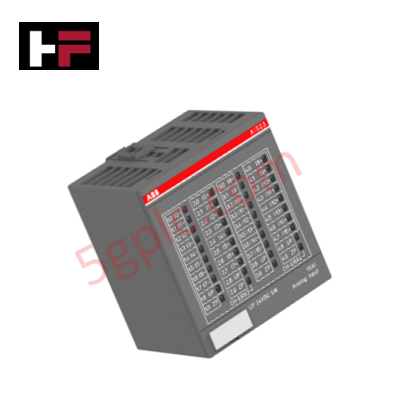
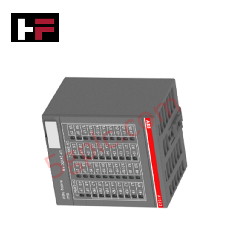
Configured for multi-channel analog signal processing in S500 automation platforms, the ABB AI531 1SAP250600R0001 (AI531 Analog input module) provides direct physical/electrical execution. The module samples peripheral sensor data from up to eight discrete channels, supporting variable wiring typologies across voltage, current, temperature, and discrete circuits.
Hardware Specifications
| Parameter | Specification |
|---|---|
| Model | AI531 |
| Brand | ABB |
| Origin | Germany |
| Weight | 0.128 kg net / 0.153 kg gross |
| Dimensions | 67.5 mm x 76 mm x 62 mm (W x H x D) |
| Operating Temp | 0 to +60 deg C (Standard industrial baseline) |
| Power Consumption | Driven by 24 VDC terminal/backplane interface |
| Channel Density | 8 Analog Inputs |
| Input Signal Types | Voltage (U), Current (I), RTD, Resistance (R), Thermocouple (TC), Digital Input (DI) |
| Resolution | 16-bit resolution including sign |
| Wiring Configuration | 1 to 4-wire configuration |
| Degree of Protection | IP20 |
Deterministic Networks & I/O Density Scaling
The internal architecture leverages discrete I/O density scaling to interface mixed sensor signals within a uniform terminal footprint. Data updates are synchronized over Profinet / EtherNet/IP deterministic networks via the local terminal base backplane bus. The hardware accommodates firmware flash compatibility sequences to match host CPU revisions, maintaining microsecond-level register mapping without compromising channel-to-channel signal isolation boundaries during high-density cyclic data transfers.
Frequently Asked Questions
Q: Does the AI531 module support hot-swap extraction under active backplane bus operation?
A: No. Removal of the active electronic module from the terminal base under power can corrupt synchronous communication on the local backplane bus and trigger unexpected fault conditions in the master processor module.
Q: How is the 16-bit conversion accuracy optimized when mixing thermocouples and current loops?
A: Each input channel parameter register must be configured individually via the engineering software to select the target signal characteristic. Internal cold junction compensation or loop scaling parameters adapt the internal hardware conversion circuits based on the active selection matrix.
Q: What is the mechanical layout constraint for the 1 to 4-wire connection configurations?
A: Wire termination paths map directly to the corresponding terminal block base unit. Four-wire RTD or resistance setups occupy dedicated layout structures to eliminate lead wire resistance errors without requiring external hardware bridges.
Field Installation Guidelines
- Mount the assembly horizontally or vertically onto a standard 35 mm DIN rail ensuring the grounding clip establishes explicit mechanical electrical continuity.
- Shield braid terminations for analog signaling loops must be grounded at a single low-impedance potential point inside the control enclosure.
- Separate low-voltage analog signal cables from high-voltage power distribution conduits by a minimum clearance of 100 mm to mitigate electromagnetic cross-talk.
- Secure all terminal block retention screws to standard torque limits to ensure mechanical stability under high-vibration operational environments.
Additional Information
- 100% Genuine Parts: All products are original and authentic, ensuring reliable industrial performance.
- 30-Day Refund Guarantee: Return any in-stock item within 30 days in original, unopened packaging for a full refund (excluding shipping and fees).
- 12-Month Warranty: Covers defects in materials or workmanship; excludes misuse, normal wear, or unauthorized modifications.
- Worldwide Shipping: We ship via USPS, UPS, FedEx, and DHL. Delivery times vary by country and may be subject to customs or import fees.
- Support & Contact: Technical and warranty assistance is available anytime. Contact us here: Contact.
- Purchase Guidance: Check product specifications and compatibility carefully before ordering to ensure proper application.
Tech & Buying Guide

Core Components of Programmable Logic Controllers (PLC) in Industrial Automation
A Programmable Logic Controller (PLC) serves as the digital backbone of modern factory automation. Whether you are managing complex assembly lines or simple process loops, understanding the hardware and software architecture of a PLC is essential for any control systems engineer.

PLC vs. PC: Navigating the Architectural Differences in Industrial Automation
In the realm of factory automation, professionals often debate the roles of Programmable Logic Controllers (PLCs) and Personal Computers (PCs). While both devices share fundamental computing architectures—including a processor, memory, and an operating system—their design philosophies diverge significantly. Understanding these distinctions is critical for selecting the right hardware for your industrial control systems.

Essential SCADA Features for Modern IoT-Enabled Industrial Automation
The convergence of traditional SCADA systems with the Industrial Internet of Things (IIoT) has redefined factory automation. Choosing a robust platform requires more than just standard monitoring capabilities. In this era of Industry 4.0, your supervisory system must bridge the gap between legacy control systems and enterprise-level data integration.