


Product Details
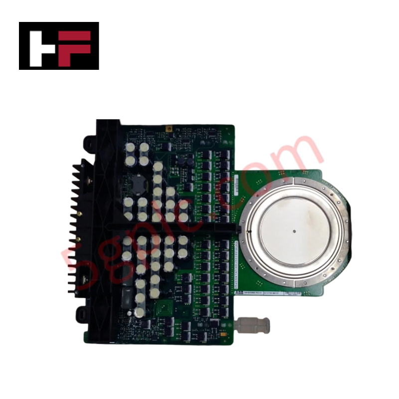
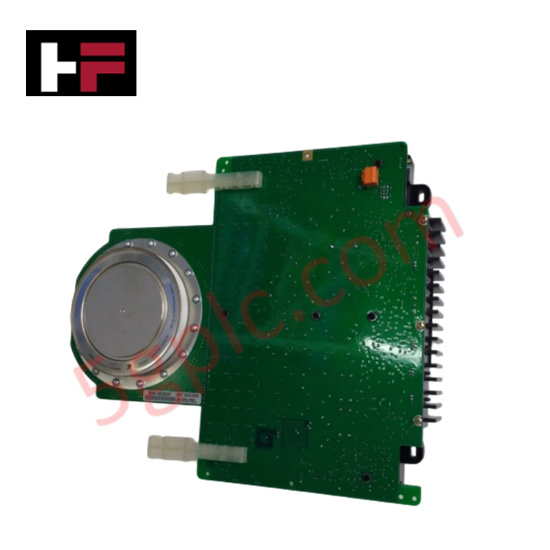
The ABB 5SHY3545L0021 AC10272001R0101, also cataloged as the 5SHY3545L0021 IGCT Module, operates as a dedicated hardware component for high-power semiconductor switching within power conversion networks. Configured to manage solid-state circuit commutation path execution, the unit acts directly across the high-voltage lines using its integrated gate-drive circuitry to regulate state transitions.
Hardware Specifications
| Parameter | Specification |
|---|---|
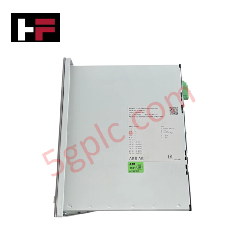
| Model | 5SHY3545L0021 |
| Brand | ABB |
| Designator ID | AC10272001R0101 |
| Origin | Sweden / Switzerland |
| Rated Voltage | 6500 V |
| Rated Current | 1000 A |
| Switching Frequency | Up to 2 kHz |
| Efficiency Profile | Low conduction and switching losses |
| Max Junction Temperature | 175 deg C |
| Net Dimensions | 300 mm x 250 mm x 150 mm |
| Net Weight | 1.5 kg |
| Power Consumption | Determined by active gate frequency and load configurations |
Profinet / EtherNet/IP Deterministic Networks Alignment
Operational gating pulses within this module depend directly upon synchronous coordination across the drive architecture. To achieve rapid conduction state commutation up to 6500 V, the internal layout interfaces with control protocols that match specific backplane bus communication velocity metrics. System integration requires high I/O density scaling profiles, verifying absolute firmware flash compatibility across connected controller hardware to remove packet latency errors or pulse translation jitter over deterministic networks.
Frequently Asked Questions
Q: Does the 5SHY3545L0021 AC10272001R0101 board support hot-swapping or live modifications?
A: No. Hot-swapping this device is entirely restricted. All main power links up to 6500 V and auxiliary driver board power buses must be completely isolated and verified discharged prior to mechanical or electrical servicing.
Q: What mechanism is used to deliver the switching triggers to the gate?
A: Firing triggers and timing execution metrics are transmitted via optical fiber links to ensure high electrical isolation and immunity against surrounding electromagnetic interference fields.
Q: How is the maximum temperature specification defined for this unit?
A: The design permits a maximum semiconductor junction temperature limit of 175 deg C. Proper mechanical clamp force and cooling baseplate integration are required to prevent thermal overloading.
Field Installation Guidelines
- Press-Pack Mounting Force Balance: Position the unit inside the calibrated mounting clamp frame. Apply mechanical compression evenly across the contact surfaces to prevent asymmetric physical stress on the silicon wafer inside the capsule.
- Fiber Optic Layout Control: Protect all fiber optic interfaces from sharp bends. Adhere to specified minimum bending radii thresholds to eliminate signal degradation or micro-fractures in the data paths.
- Mating Surface Cleaning: Ensure that all physical cooling blocks are cleaned of residual oxides. Apply a uniform, ultra-thin coating of non-conductive thermal paste before completing mechanical assembly fasteners.
Additional Information
- 100% Genuine Parts: All products are original and authentic, ensuring reliable industrial performance.
- 30-Day Refund Guarantee: Return any in-stock item within 30 days in original, unopened packaging for a full refund (excluding shipping and fees).
- 12-Month Warranty: Covers defects in materials or workmanship; excludes misuse, normal wear, or unauthorized modifications.
- Worldwide Shipping: We ship via USPS, UPS, FedEx, and DHL. Delivery times vary by country and may be subject to customs or import fees.
- Support & Contact: Technical and warranty assistance is available anytime. Contact us here: Contact.
- Purchase Guidance: Check product specifications and compatibility carefully before ordering to ensure proper application.


Tech & Buying Guide

PLC vs. PC: Navigating the Architectural Differences in Industrial Automation
In the realm of factory automation, professionals often debate the roles of Programmable Logic Controllers (PLCs) and Personal Computers (PCs). While both devices share fundamental computing architectures—including a processor, memory, and an operating system—their design philosophies diverge significantly. Understanding these distinctions is critical for selecting the right hardware for your industrial control systems.

Essential SCADA Features for Modern IoT-Enabled Industrial Automation
The convergence of traditional SCADA systems with the Industrial Internet of Things (IIoT) has redefined factory automation. Choosing a robust platform requires more than just standard monitoring capabilities. In this era of Industry 4.0, your supervisory system must bridge the gap between legacy control systems and enterprise-level data integration.
Selecting Rockwell Automation Allen-Bradley PLCs for Small and Mid-Sized Applications
Rockwell Automation remains a cornerstone in global industrial automation. Their Allen-Bradley brand provides a comprehensive portfolio of control systems designed to meet diverse production requirements. Choosing the right programmable logic controller (PLC) is critical for system reliability and scalability. This guide analyzes the Micro and Compact Logix families to help you select the optimal solution for small and medium-scale projects.