











Product Details
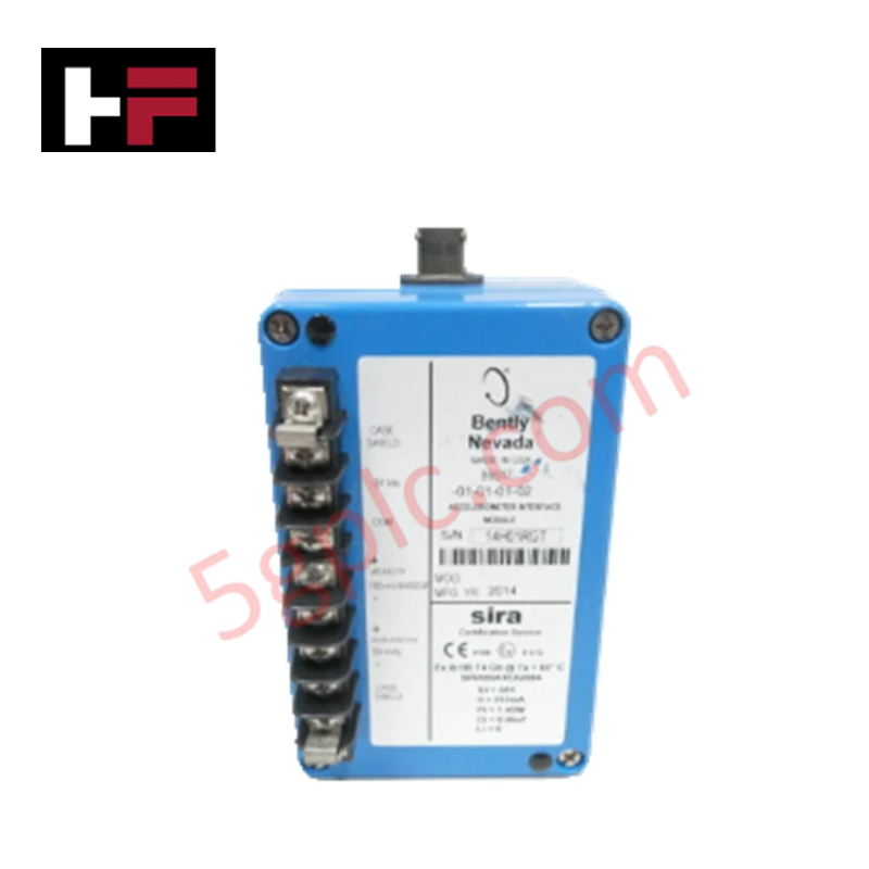
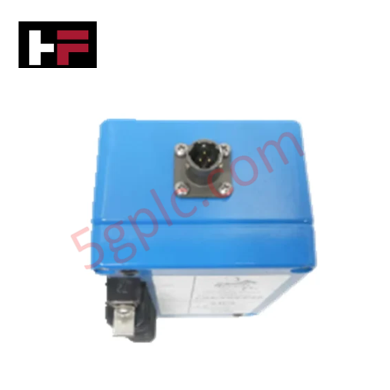
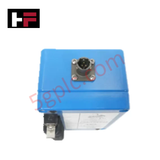
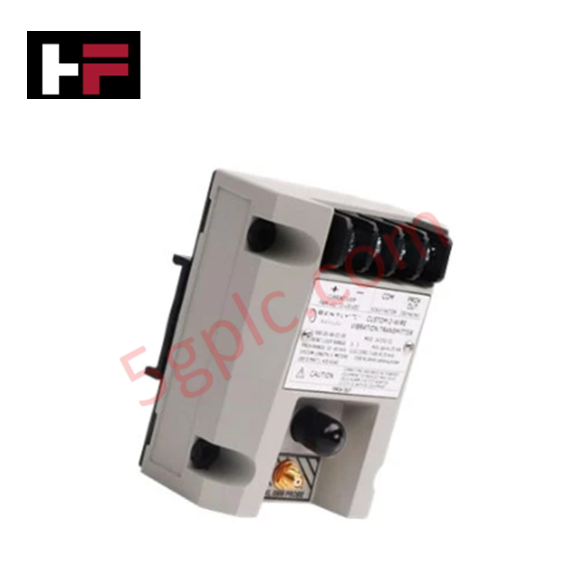
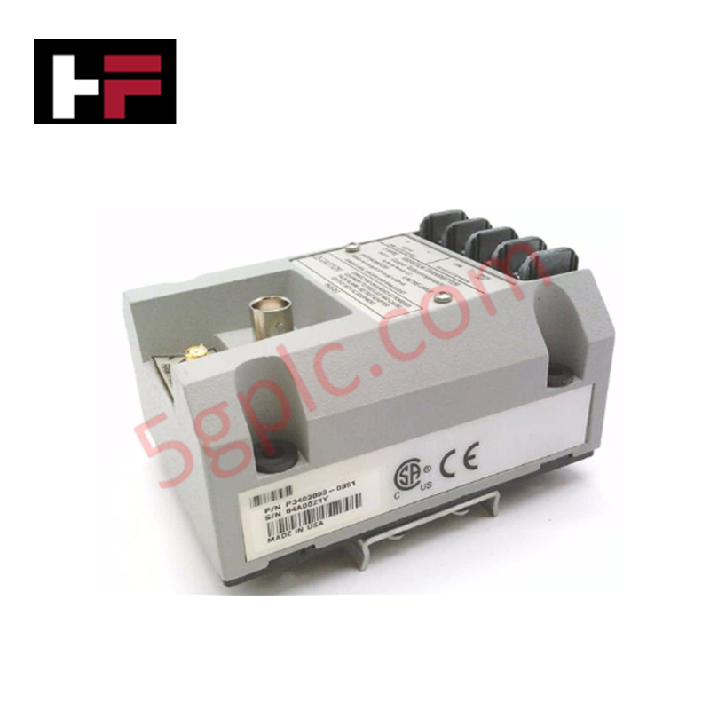
Configured for dynamic charge signal conditioning in Bently Nevada monitoring networks, the Bently Nevada 86517-01-01-01-02 (86517 Acceleration Interface Module) provides direct physical/electrical execution.
Suffix Breakdown & Model Matrix
| Option Field | Code | Configuration Detail |
|---|---|---|
| Transducer Charge Input Sensitivity | 01 | 50 pC/g input scaling |
| Filter Corner Frequency | 01 | 25 Hz high-pass corner / 350 Hz low-pass corner |
| DC Signal Bias Voltage | 01 | -10 VDC bias voltage |
| Agency Approval | 02 | CENELEC (SIRA) hazardous area approval |
Hardware Specifications
| Parameter | Specification |
|---|---|
| Model | 86517-01-01-01-02 |
| Brand | Bently Nevada |
| Origin | USA |
| Weight | Shipping weight: 2.0 kg |
| Dimensions | 13.97 cm x 8.26 cm x 7.62 cm |
| Operating Temp | -30 deg C to +65 deg C |
| Power Consumption | Powered via system backplane or external loop supply |
| Transducer Sensitivity | 50 pC/g |
| Passband Filter Limits | 25 Hz high-pass corner to 350 Hz low-pass corner |
| DC Bias Voltage | -10 VDC |
| Certification | CENELEC (SIRA) |
Rotor Dynamics and Signal Conditioning Execution
The 86517-01-01-01-02 interface module processes high-impedance charge signals from piezoelectric accelerometers into low-impedance voltage signals suitable for machinery monitoring instrumentation. Integrated filtering limits the passband between 25 Hz and 350 Hz to eliminate low-frequency baseline roll and high-frequency structural noise. Maintaining a stable -10 VDC bias voltage target supports precise dynamic vibration spectral analysis and rotor dynamics tracking while suppressing cross-talk across adjacent signal cabling runs.
Frequently Asked Questions
Q: What transducer charge sensitivity range is supported by Option 01?
A: Option 01 configures the internal charge amplifier circuit for an input scaling sensitivity of 50 pC/g.
Q: How does the filtering circuit shape the acceleration signal band?
A: The module applies a 25 Hz high-pass corner filter combined with a 350 Hz low-pass corner filter to attenuate unwanted out-of-band noise before outputting the analog signal.
Field Installation Guidelines
- Mount the module chassis securely to the enclosure frame or sub-panel using designated mounting holes.
- Route high-impedance accelerometer charge cables separately from power supply conductors and switching lines.
- Connect signal leads and shield drain wires to the designated terminal blocks, ensuring shields are grounded at a single point only.
- Verify that the DC bias voltage reads -10 VDC under static operating conditions using a calibrated multimeter.
- Secure all terminal screws to recommended tightening torque limits to maintain reliable contact resistance over extended operating periods.
Additional Information
- 100% Genuine Parts: All products are original and authentic, ensuring reliable industrial performance.
- 30-Day Refund Guarantee: Return any in-stock item within 30 days in original, unopened packaging for a full refund (excluding shipping and fees).
- 12-Month Warranty: Covers defects in materials or workmanship; excludes misuse, normal wear, or unauthorized modifications.
- Worldwide Shipping: We ship via USPS, UPS, FedEx, and DHL. Delivery times vary by country and may be subject to customs or import fees.
- Support & Contact: Technical and warranty assistance is available anytime. Contact us here: Contact.
- Purchase Guidance: Check product specifications and compatibility carefully before ordering to ensure proper application.


Tech & Buying Guide
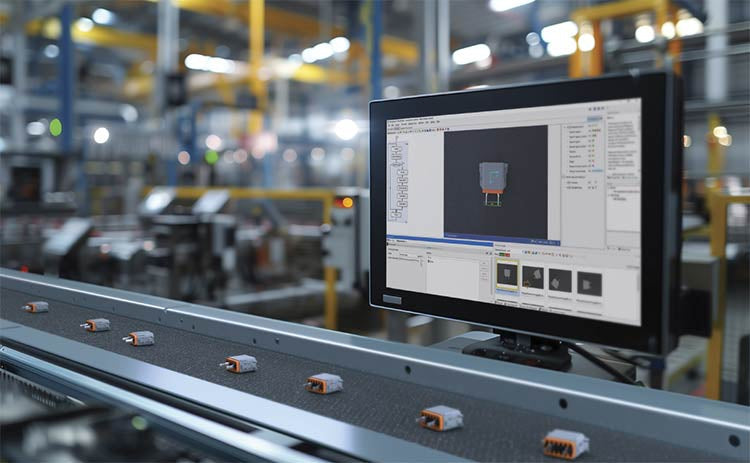
Modern Industrial Automation: Transforming Safety and Efficiency in Mining Operations
Industrial automation has evolved from a simple manufacturing tool into the operational backbone of high-risk sectors. Modern mining operations increasingly rely on advanced control systems, programmable logic controllers (PLCs), distributed control systems (DCS), and artificial intelligence to address deep-underground hazards. By replacing manual labor in high-risk zones, factory automation technologies protect personnel while significantly boosting operational throughput.

Step-by-Step System Cabinet Health Check Guide for PLC and DCS Infrastructure
