










Product Details
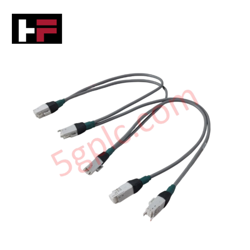
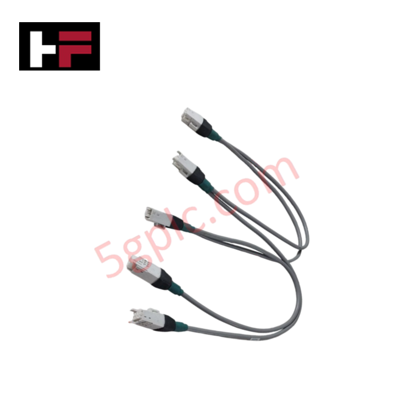
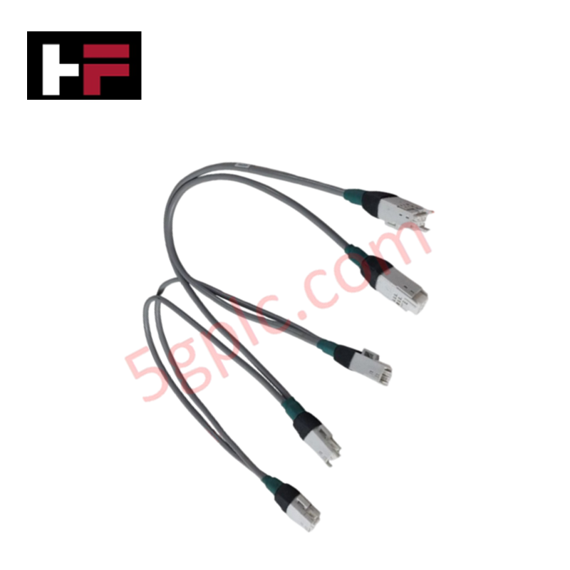
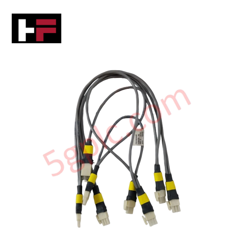
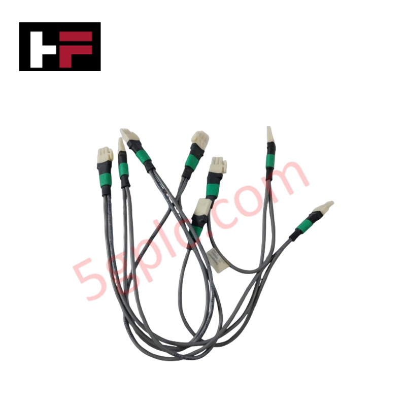
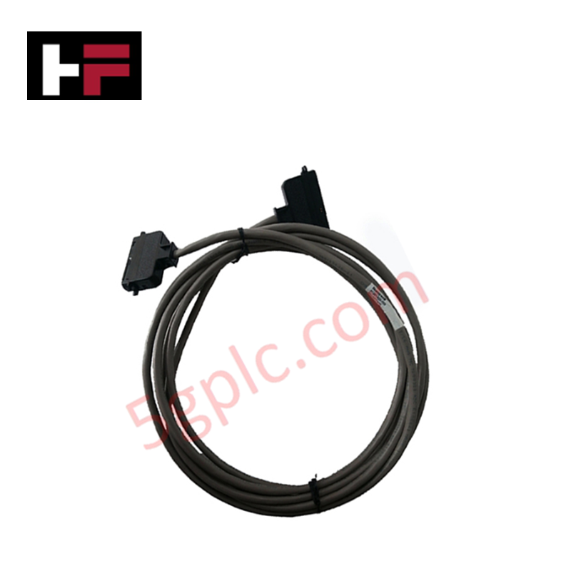
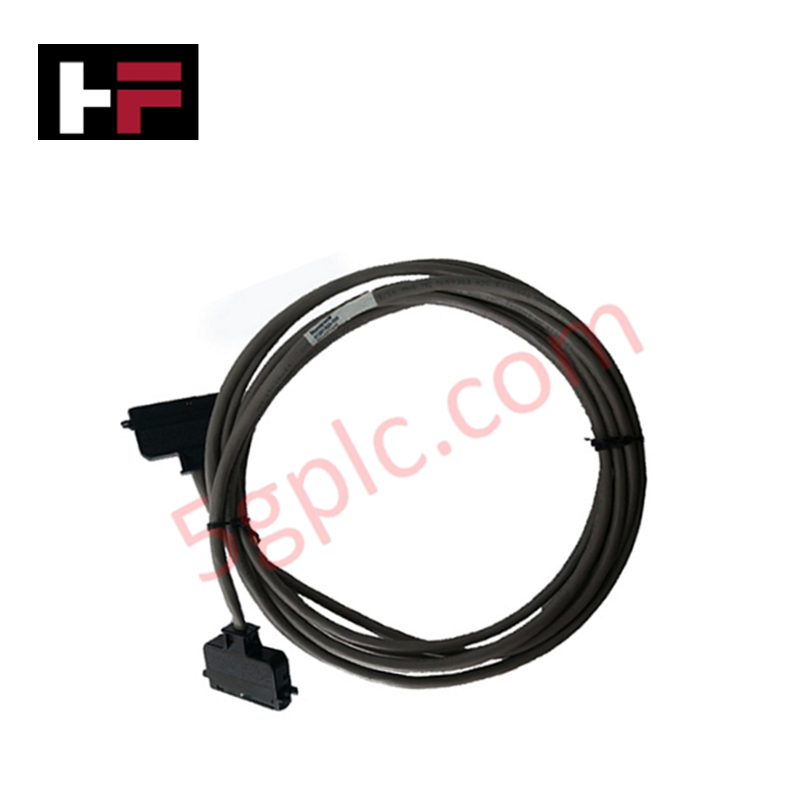
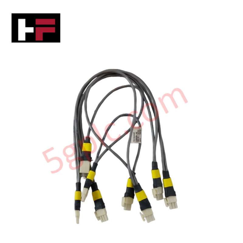
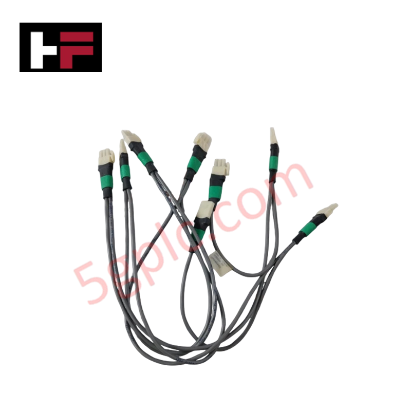
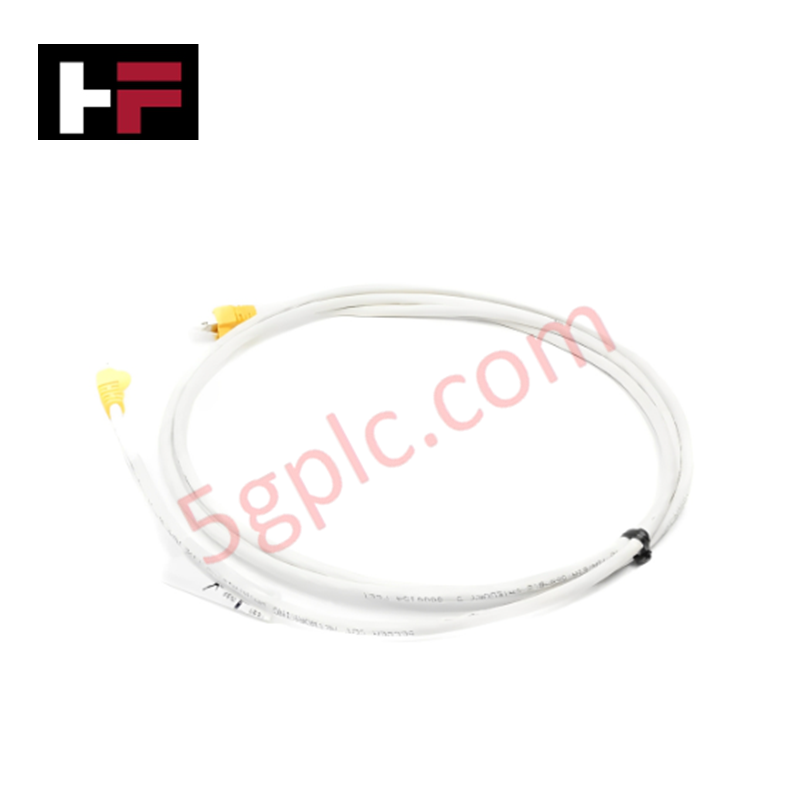
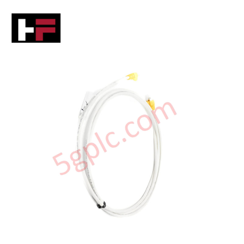
The Honeywell 51204037-005, also cataloged as the 51204037 Shielded Power Distribution Cable, operates as a dedicated hardware component for low-loss 24 VDC bus power routing within Honeywell DCS control enclosures.
Hardware Specifications
| Parameter | Specification |
|---|---|
| Model | 51204037-005 |
| Brand | Honeywell |
| Origin | USA |
| Weight | Approx. 0.45 kg |
| Dimensions | 5.0 m length |
| Operating Temp | -20 deg C to +70 deg C |
| Power Consumption | Passive power conductor (24 VDC rated) |
| Voltage Rating | 24 VDC nominal |
| Cable Type | Shielded Power Distribution Assembly |
| Shielding Type | Full metallic EMI suppression shield |
| Cable Length | 5 meters |
4-20 mA HART Loop Protocol and Channel-to-Channel Isolation
The power assembly incorporates continuous braided shielding surrounding all 24 VDC conductors to suppress electromagnetic interference (EMI) radiation within high-density instrument racks. By maintaining a grounded dielectric barrier between power distribution lines and adjacent signal harnesses, the cable prevents high-frequency switching noise from corrupting field loops executing the 4-20 mA HART loop protocol or degrading channel-to-channel isolation references across sensitive I/O cards.
Frequently Asked Questions
Q: What is the primary purpose of the internal metallic shield in the 51204037-005 power cable?
A: The shield attenuates radiated electromagnetic noise (EMI), preventing high-frequency transients on the 24 VDC power rail from coupling into nearby low-voltage signal lines.
Q: How is the overall shield grounded during field cabinet assembly?
A: The cable braid must be terminated to a dedicated cabinet earth ground bar at one end using a low-impedance clamp to ensure effective noise dissipation.
Field Installation Guidelines
- De-energize 24 VDC supply breakers prior to mating or unmating cable connectors.
- Route power cables in dedicated cabinet wire trays separate from high-density analog and digital communication lines.
- Ensure the overall braid shield connects directly to chassis earth ground at the distribution panel end.
- Observe minimum bend radius limits along raceway corners to protect internal conductors and shield integrity.
Additional Information
- 100% Genuine Parts: All products are original and authentic, ensuring reliable industrial performance.
- 30-Day Refund Guarantee: Return any in-stock item within 30 days in original, unopened packaging for a full refund (excluding shipping and fees).
- 12-Month Warranty: Covers defects in materials or workmanship; excludes misuse, normal wear, or unauthorized modifications.
- Worldwide Shipping: We ship via USPS, UPS, FedEx, and DHL. Delivery times vary by country and may be subject to customs or import fees.
- Support & Contact: Technical and warranty assistance is available anytime. Contact us here: Contact.
- Purchase Guidance: Check product specifications and compatibility carefully before ordering to ensure proper application.
Tech & Buying Guide

Comprehensive Guide to Instrumentation and Control (I&C) Design Basis
Instrumentation and Control (I&C) Design Basis serves as the foundational technical document for modern plant engineering. Project teams rely on this master specification to govern engineering deliverables across front-end engineering design (FEED) and detailed execution phases. A well-constructed I&C design basis ensures seamless integration among field instrumentation, safety systems, and main control systems. Furthermore, establishing clear technical standards early mitigates execution risks and prevents costly re-engineering during plant commissioning.

The Shift to Flexible IO Modules in Modern Industrial Automation
Traditional control systems rely on dedicated Input Output (IO) cards for industrial automation. Each conventional module processes a single signal type, such as Digital Input (DI), Digital Output (DO), Analog Input (AI), or Analog Output (AO). A standard 16-channel card accepts only one specific channel type across all ports. This inflexible hardware design often creates severe engineering bottlenecks during project execution. Engineers frequently must install entirely new cards to accommodate a single extra sensor. Consequently, late design changes increase control cabinet space requirements and drive up project costs.

DCS Commissioning Steps in Industrial Automation Projects
Commissioning a Distributed Control System (DCS) represents a crucial milestone when deploying modern process automation infrastructure. Field engineers must execute systematic verification steps to transition complex control hardware from static installation to dynamic plant control. Proper commissioning ensures that controllers, I/O modules, network switches, and HMI software operate in strict compliance with engineering design specifications before introducing live process fluids.