


Product Details
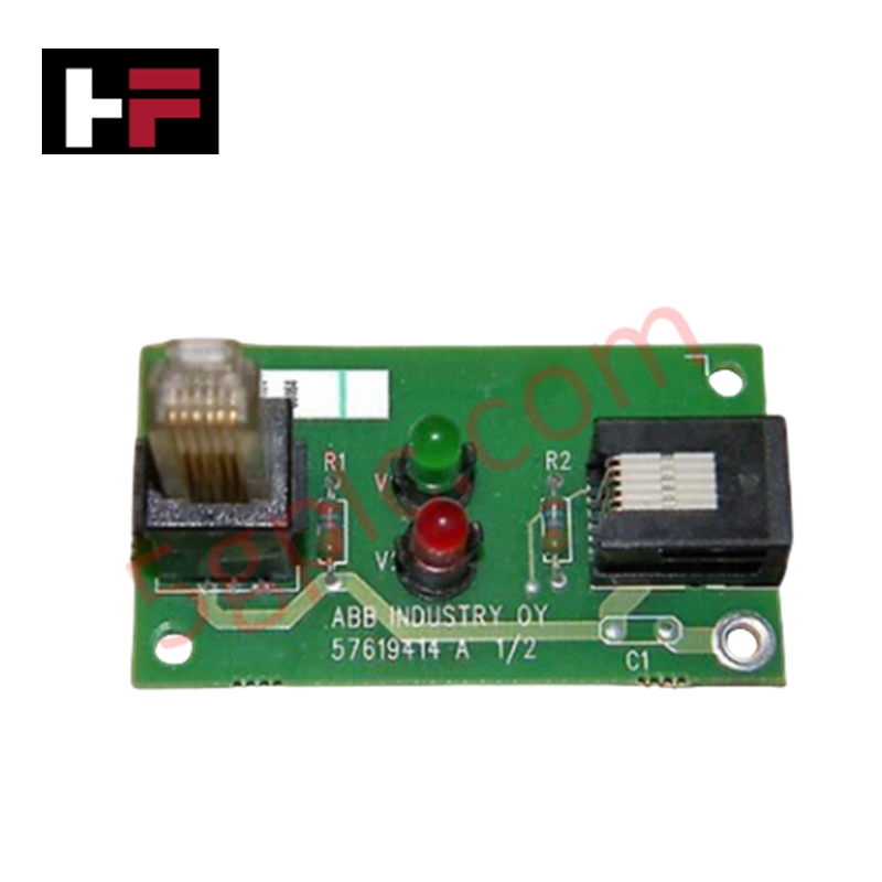
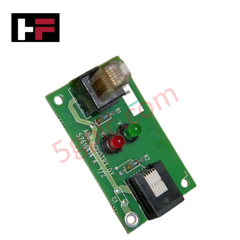
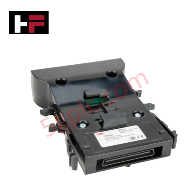
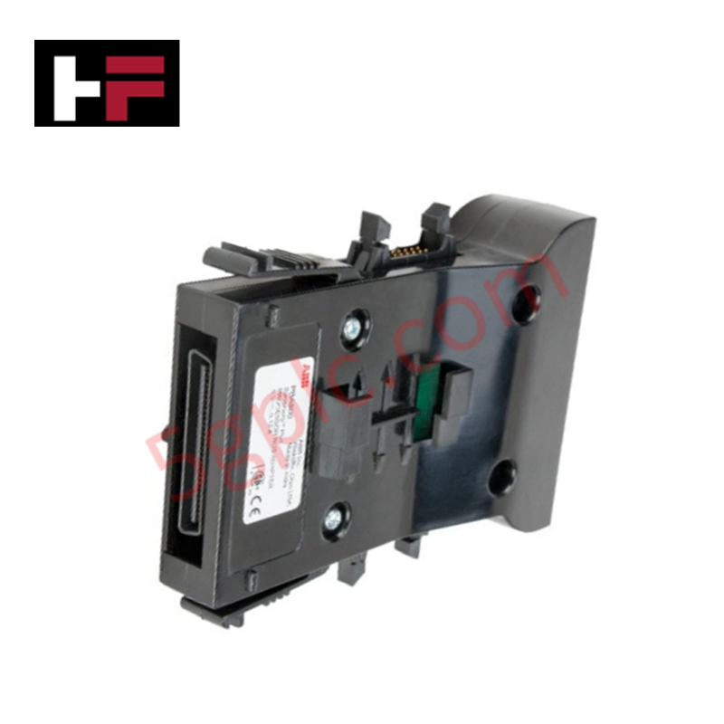
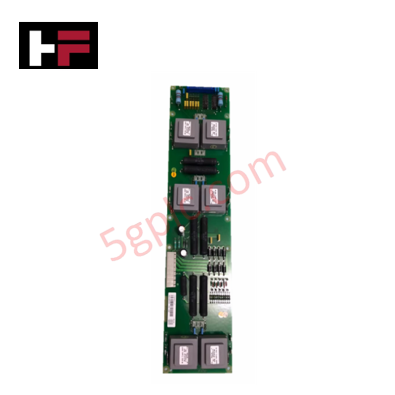
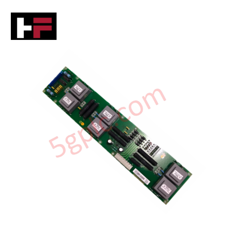
The ABB 3BHL000764P0001, also cataloged as the NDPI-02 Connection Board, operates as a dedicated hardware component for physical signal routing and line termination within industrial drive and control platforms.
Hardware Specifications
| Parameter | Specification |
|---|---|
| Model | NDPI-02 (3BHL000764P0001) |
| Brand | ABB |
| Origin | Sweden |
| Weight | 0.05 kg |
| Dimensions | Standard internal drive housing PCB dimensions |
| Operating Temp | 0 to +60 deg C standard internal enclosure ambient |
| Power Consumption | Passive circuit trace interface matching load |
| Product Type | Connection Boards |
| Frame Size Class | Spare Parts |
| Unit Package | 1 piece |
Backplane Bus Communication Velocity and Signal Routing Integrity
The ABB NDPI-02 connection board coordinates the direct interface pathways between processing cards and peripheral drive subsystems. It acts to maintain constant internal signal bus continuity without generating signal phase delays or timing skew. The board geometry layout is engineered to withstand voltage fluctuation and control frequency shifts on industrial network configurations, preventing signal loss across localized circuit networks. This ensures firmware flash compatibility parameters are preserved across active system components by protecting communication line traces from capacitive distortions during synchronous execution blocks.
Frequently Asked Questions
Q: Is the NDPI-02 connection board designed for hot-swap installation?
A: No. The board features passive physical pin headers and trace pathways that lack active isolation barriers. Power feeds to the primary system chassis must be locked out prior to card handling to avoid electrical shorts.
Q: How is physical alignment ensured during chassis mounting?
A: The board features pre-drilled trace spacing holes configured to match the localized mounting standoffs inside standard compatible ABB drive cubicles or rack cages, ensuring terminal pin alignment.
Field Installation Guidelines
- Disconnect and lock out all upstream electrical power supplies to the target system frame before unboxing or mounting the board.
- Use an approved electrostatic discharge (ESD) wrist strap connected to earth ground during the extraction and placement procedures.
- Slide the board onto its interior retention standoffs, ensuring all pin headers seat into the corresponding mate sockets without bending the mechanical pins.
- Tighten all localized retention fasteners to standard torques to achieve mechanical bonding and ground plane integration with the master chassis.
Additional Information
- 100% Genuine Parts: All products are original and authentic, ensuring reliable industrial performance.
- 30-Day Refund Guarantee: Return any in-stock item within 30 days in original, unopened packaging for a full refund (excluding shipping and fees).
- 12-Month Warranty: Covers defects in materials or workmanship; excludes misuse, normal wear, or unauthorized modifications.
- Worldwide Shipping: We ship via USPS, UPS, FedEx, and DHL. Delivery times vary by country and may be subject to customs or import fees.
- Support & Contact: Technical and warranty assistance is available anytime. Contact us here: Contact.
- Purchase Guidance: Check product specifications and compatibility carefully before ordering to ensure proper application.
Tech & Buying Guide
Industrial PC vs. Commercial PC: Selecting the Right Hardware for Automation
In the demanding world of factory automation, selecting the correct computing platform is critical for system reliability. While commercial PCs power our daily lives, they often fail when subjected to the harsh realities of the production floor. Understanding the fundamental differences between an Industrial PC (IPC) and a standard office PC helps engineers optimize control systems for longevity and performance.

Core Components of Programmable Logic Controllers (PLC) in Industrial Automation
A Programmable Logic Controller (PLC) serves as the digital backbone of modern factory automation. Whether you are managing complex assembly lines or simple process loops, understanding the hardware and software architecture of a PLC is essential for any control systems engineer.

PLC vs. PC: Navigating the Architectural Differences in Industrial Automation
In the realm of factory automation, professionals often debate the roles of Programmable Logic Controllers (PLCs) and Personal Computers (PCs). While both devices share fundamental computing architectures—including a processor, memory, and an operating system—their design philosophies diverge significantly. Understanding these distinctions is critical for selecting the right hardware for your industrial control systems.