


Product Details
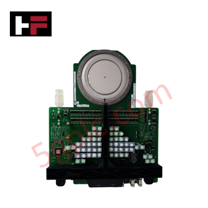
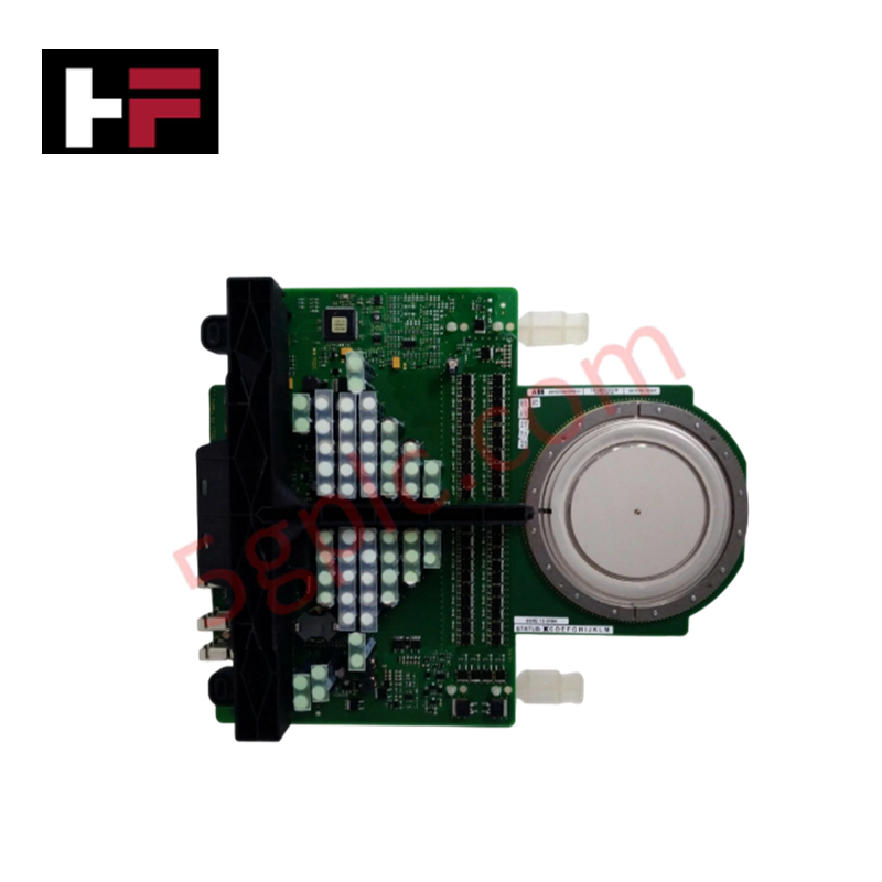
The ABB 3BHE009681R0101, also cataloged as the 3BHE009681R0101 IGCT Module, operates as a dedicated hardware component for high-power semiconductor switching within industrial power conversion and drive systems. The module integrates the 3BHB012961R0001 gate unit and the 5SHX2645L0002 thyristor element to execute solid-state circuit commutation with fast switching transitions and low conduction losses.
Hardware Specifications
| Parameter | Specification |
|---|---|
| Model | 3BHE009681R0101 |
| Brand | ABB |
| Sub-Assembly Models | 3BHB012961R0001 / 5SHX2645L0002 |
| Origin | Sweden / Switzerland |
| Weight | 2.5 kg |
| Dimensions | 120 mm x 120 mm x 100 mm |
| Operating Temp | Standard industrial range (Refer to system enclosure limits) |
| Power Consumption | Dependent on switching frequency and gate drive load |
| Semiconductor Type | Integrated Gate-Commutated Thyristor (IGCT) |
Deterministic Network and Firmware Flash Compatibility
The integrated gate driver card requires direct synchronization with the host controller to maintain precise turn-on and turn-on timing. Firmware flash compatibility between the gate control subsystem and the primary application controller prevents pulse-width modulation (PWM) errors and unexpected commutation failures. Operational commands are processed via low-latency physical interfaces, ensuring high-speed switching response times that maintain loop stability inside demanding industrial control and multi-phase drive topologies.
Frequently Asked Questions
Q: What is the hot-swap limitation for this IGCT module assembly?
A: This module does not support hot-swapping. Complete isolation from all high-voltage power sources and control bus voltages is mandatory before extraction or insertion to prevent physical destruction or severe electrical arcing.
Q: How do the individual part numbers interact within this module?
A: The 3BHE009681R0101 represents the master system assembly identifier, which structurally combines the 3BHB012961R0001 gate controller logic hardware and the 5SHX2645L0002 physical silicon thyristor disk.
Q: What defines the operational current and power consumption limits of the control circuit?
A: The control side power consumption is determined by the internal gate driver charging circuit and varies linearly based on the operating switching frequency applied by the master pulse generator.
Field Installation Guidelines
- Bus Bar Contact Pressure: Secure the module within the clamping assembly using the exact factory-specified force matrix. Incorrect mounting pressure increases contact resistance, which leads to localized thermal runaway at the high-power interfaces.
- Control Harness Separation: Route the low-voltage gate power and optical command lines completely separate from any main phase bus bars or high-frequency motor output conductors to minimize inductive signal cross-talk.
- Thermal Interface Management: Clean the heatsink surface completely and apply a thin, uniform layer of non-curing thermal compound before mounting to facilitate optimized heat rejection through the base plate.
Additional Information
- 100% Genuine Parts: All products are original and authentic, ensuring reliable industrial performance.
- 30-Day Refund Guarantee: Return any in-stock item within 30 days in original, unopened packaging for a full refund (excluding shipping and fees).
- 12-Month Warranty: Covers defects in materials or workmanship; excludes misuse, normal wear, or unauthorized modifications.
- Worldwide Shipping: We ship via USPS, UPS, FedEx, and DHL. Delivery times vary by country and may be subject to customs or import fees.
- Support & Contact: Technical and warranty assistance is available anytime. Contact us here: Contact.
- Purchase Guidance: Check product specifications and compatibility carefully before ordering to ensure proper application.


Tech & Buying Guide

PLC vs. PC: Navigating the Architectural Differences in Industrial Automation
In the realm of factory automation, professionals often debate the roles of Programmable Logic Controllers (PLCs) and Personal Computers (PCs). While both devices share fundamental computing architectures—including a processor, memory, and an operating system—their design philosophies diverge significantly. Understanding these distinctions is critical for selecting the right hardware for your industrial control systems.

Essential SCADA Features for Modern IoT-Enabled Industrial Automation
The convergence of traditional SCADA systems with the Industrial Internet of Things (IIoT) has redefined factory automation. Choosing a robust platform requires more than just standard monitoring capabilities. In this era of Industry 4.0, your supervisory system must bridge the gap between legacy control systems and enterprise-level data integration.
Selecting Rockwell Automation Allen-Bradley PLCs for Small and Mid-Sized Applications
Rockwell Automation remains a cornerstone in global industrial automation. Their Allen-Bradley brand provides a comprehensive portfolio of control systems designed to meet diverse production requirements. Choosing the right programmable logic controller (PLC) is critical for system reliability and scalability. This guide analyzes the Micro and Compact Logix families to help you select the optimal solution for small and medium-scale projects.