










Product Details
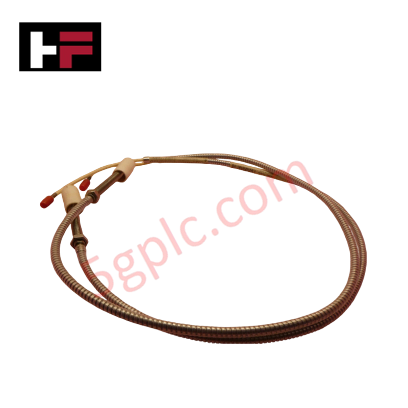
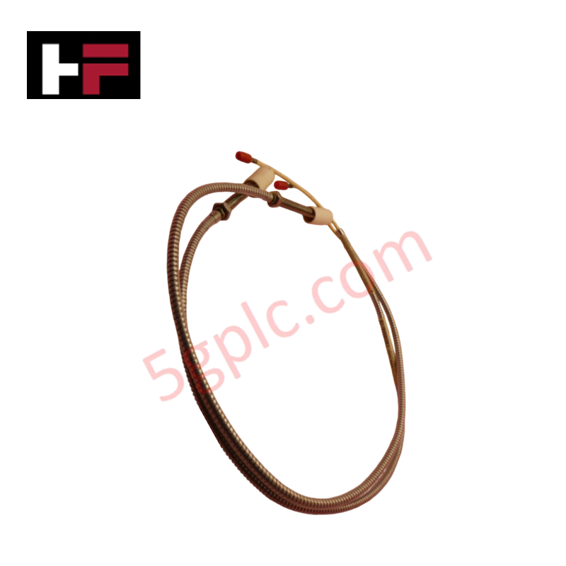
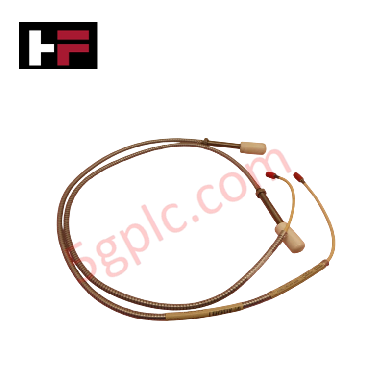
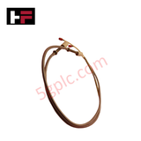
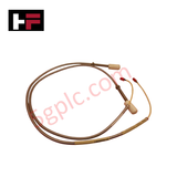
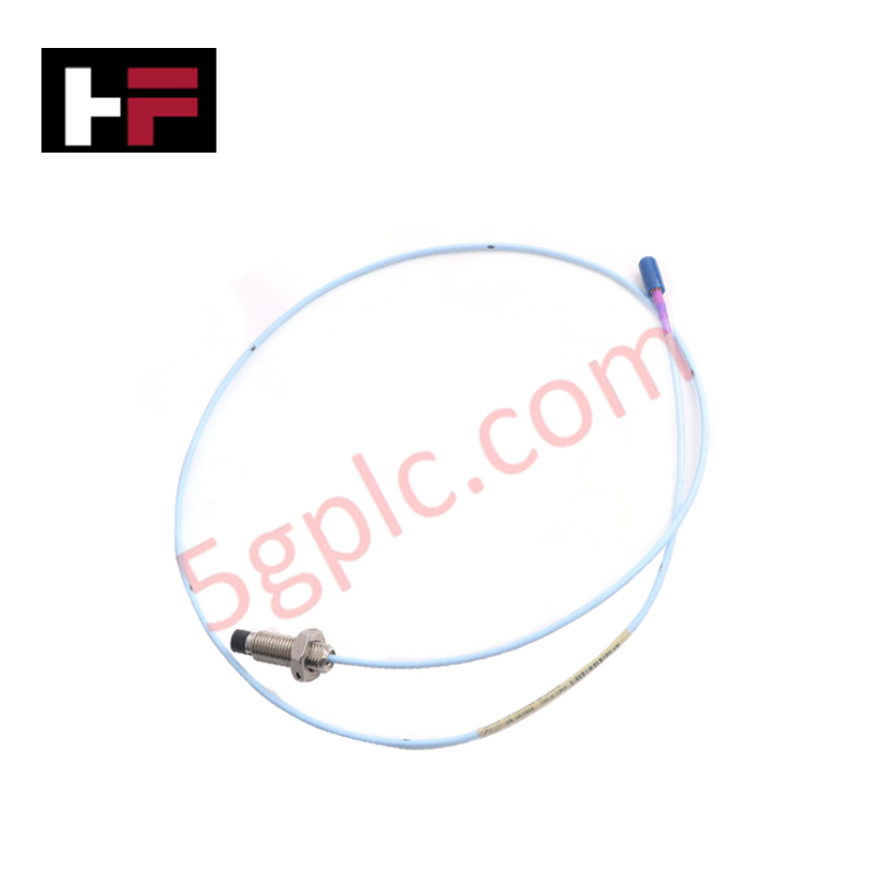
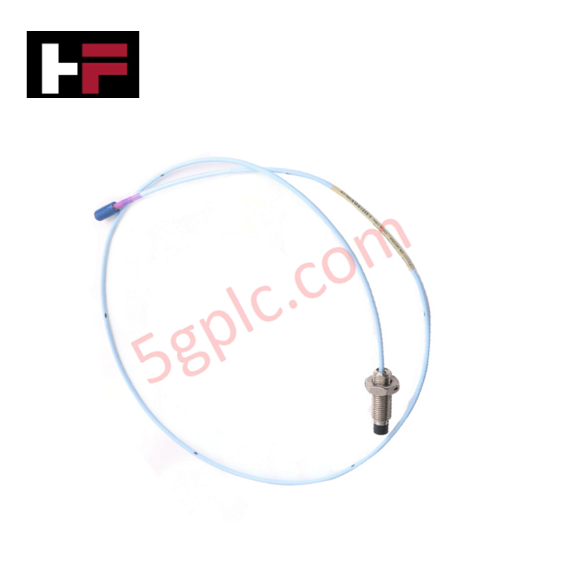
The Bently Nevada 21505-00-36-10-02, also cataloged as the 21505 Proximity Probe Sensor, operates as a dedicated hardware component for non-contacting radial vibration and axial position measurement within Bently Nevada 7200 Series machinery monitoring platforms.
Hardware Specifications
| Parameter | Specification |
|---|---|
| Model | 21505-00-36-10-02 |
| Brand | Bently Nevada |
| Origin | USA / As specified on hardware label |
| Weight | Standard probe assembly weight (~0.25 kg) |
| Dimensions | 36 in cable length, 3/8-24 UNF thread body |
| Operating Temp | -40 to 177 deg C |
| Power Consumption | Driven by external Proximitor Sensor power supply |
| Transducer Type | Eddy current proximity probe |
| Linear Range | 2.0 mm (80 mils) nominal linear range |
| Output Signal | Gap-to-voltage proportional output via Proximitor |
| Mounting Thread | 3/8-24 UNF case thread |
| Cable Armor Option | Unarmored / Stainless steel armor options |
Gap Voltage Validation and Rotor Dynamics
The 21505-00-36-10-02 transducer tip emits a high-frequency RF field into target conductive shaft materials to measure dynamic rotor motion. During installation on rotating machinery, gap voltage validation targets (-10 VDC nominal target setting) establish correct mechanical probe tip distance relative to the journal surface within the linear voltage range. Proper eddy-current probe scaling ensures accurate high-speed signal conversion for rotor dynamics tracking, while internal shielding prevents cross-talk suppression issues between closely spaced radial X-Y probe pairs.
Frequently Asked Questions
Q: How is the physical gap voltage set during mechanical installation of the 21505-00-36-10-02 probe?
A: Mechanical insertion depth is adjusted while observing DC voltage output at the Proximitor monitor terminals until reaching the baseline -10 VDC gap target within the linear center zone.
Q: What is the maximum continuous temperature limit for the 21505-00-36-10-02 probe head in harsh environments?
A: The probe head and cable assembly are rated for continuous operational exposure from -40 to 177 deg C.
Field Installation Guidelines
- Thread the probe body into its mounting bracket or machine casing using standard hand tools, ensuring thread engagement avoids cable twisting.
- Set physical mechanical gap depth to achieve the target DC gap voltage using a calibrated multimeter connected to the Proximitor test points.
- Torque locking nuts according to manufacturer specs to prevent physical detachment caused by machine vibration.
- Route co-axial extension cabling through dedicated rigid metallic conduit, isolating probe lines from AC power leads and VFD drive outputs.
Additional Information
- 100% Genuine Parts: All products are original and authentic, ensuring reliable industrial performance.
- 30-Day Refund Guarantee: Return any in-stock item within 30 days in original, unopened packaging for a full refund (excluding shipping and fees).
- 12-Month Warranty: Covers defects in materials or workmanship; excludes misuse, normal wear, or unauthorized modifications.
- Worldwide Shipping: We ship via USPS, UPS, FedEx, and DHL. Delivery times vary by country and may be subject to customs or import fees.
- Support & Contact: Technical and warranty assistance is available anytime. Contact us here: Contact.
- Purchase Guidance: Check product specifications and compatibility carefully before ordering to ensure proper application.


Tech & Buying Guide

Step-by-Step System Cabinet Health Check Guide for PLC and DCS Infrastructure

Top 5 Operational Advantages of HMIs in Modern Factory Automation
