


Product Details
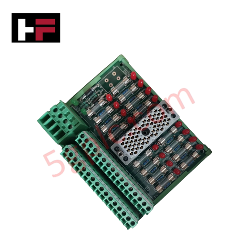
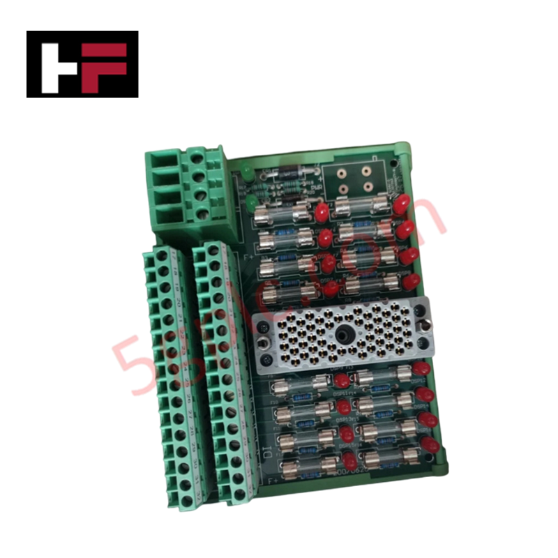
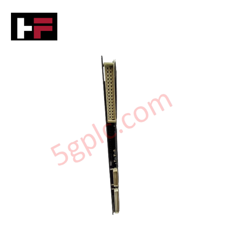
Configured for discrete status signal termination within SIS platforms, the Invensys Triconex 9563-810, also cataloged as the 9563-810 Termination Panel, provides direct physical execution for 16-point commoned digital input wiring. This hardware component serves as the interface between field devices and 32-point digital input modules, requiring two panels per module to accommodate the full 32-channel capacity.
Hardware Specifications
| Parameter | Specification |
|---|---|
| Model | 9563-810 |
| Brand | Invensys Triconex |
| Input Points | 16 commoned points |
| Leakage Current | 3.3 mA max / 2.5 mA typical |
SIS Triple Modular Redundancy (TMR) Integration
The 9563-810 panel is designed to maintain the integrity of triple modular redundancy (TMR) 2oo3 architecture by providing organized, protected signal pathways for safety-critical inputs. Each of the 16 input points is protected by an individual fuse, equipped with a visual blown-fuse indicator to facilitate rapid fault identification. This design ensures that a localized short-circuit on a single field input does not affect the remaining channels, supporting fail-safe state execution by containing faults at the termination level before they impact the primary digital input module logic.
Frequently Asked Questions
Q: How many 9563-810 panels are required for a 32-point digital input module?
A: Each 32-point digital input module (such as the 3503E or 3505E) requires two 9563-810 termination panels. The panels are supplied with labeling kits for points 1-16 and 17-32 to distinguish the two banks.
Q: What is the purpose of the PWR+ and PWR- terminals on this panel?
A: These terminals provide commoned power distribution for field devices connected to the panel, simplifying the wiring architecture for 24 VDC digital input loops.
Field Installation Guidelines
- Mount the termination panel in the cabinet using the provided mounting holes, ensuring adequate clearance for field cable strain relief.
- Verify that field wiring is connected to the commoned power terminals (PWR+ and PWR-) according to the system power distribution schematic to avoid ground loops.
- Ensure that all fuses are rated at 1 A (slow-blow) and are correctly seated to prevent nuisance trips during normal operation.
- Utilize the provided 1-16 or 17-32 labels to clearly identify the input signal mapping on each panel, ensuring consistency with the station configuration software.
- Prior to system commissioning, measure the leakage current across each point to ensure it remains within the specified range (typical 2.5 mA) and does not indicate a faulty field device or damaged wiring insulation.
Additional Information
- 100% Genuine Parts: All products are original and authentic, ensuring reliable industrial performance.
- 30-Day Refund Guarantee: Return any in-stock item within 30 days in original, unopened packaging for a full refund (excluding shipping and fees).
- 12-Month Warranty: Covers defects in materials or workmanship; excludes misuse, normal wear, or unauthorized modifications.
- Worldwide Shipping: We ship via USPS, UPS, FedEx, and DHL. Delivery times vary by country and may be subject to customs or import fees.
- Support & Contact: Technical and warranty assistance is available anytime. Contact us here: Contact.
- Purchase Guidance: Check product specifications and compatibility carefully before ordering to ensure proper application.
Tech & Buying Guide

Strategic Selection: Choosing the Right SCADA Software for Your PLC Project
In industrial automation, the SCADA (Supervisory Control and Data Acquisition) system acts as the bridge between raw machine data and actionable human intelligence. Selecting the incorrect software platform can lead to integration bottlenecks, scalability issues, and excessive long-term maintenance costs. As an automation consultant with 15 years of experience, I have guided many projects through the selection process. Below are the essential criteria for choosing a platform that ensures both performance and longevity.

Ensuring Operational Continuity: The Strategic Value of Redundant Automation Systems
In modern industrial landscapes, unplanned downtime is the ultimate adversary. For sectors relying on complex PLC and DCS architectures, a single hardware failure can trigger catastrophic production losses. Therefore, implementing redundant automation systems is no longer a luxury; it is a fundamental requirement for mission-critical operations. In this article, I analyze why redundancy remains the backbone of reliable industrial infrastructure.

Selecting the Right Cables for Industrial Automation: A Comprehensive Guide
Selecting the appropriate cabling infrastructure is critical for the success of any industrial automation project. Improper cable selection often leads to signal degradation, system instability, and costly downtime. As an automation engineer, I frequently see projects compromised by poor cabling choices in harsh industrial environments. This guide simplifies the complex landscape of cabling to help you make informed decisions for your PLC, DCS, and control systems.