











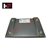
Product Details
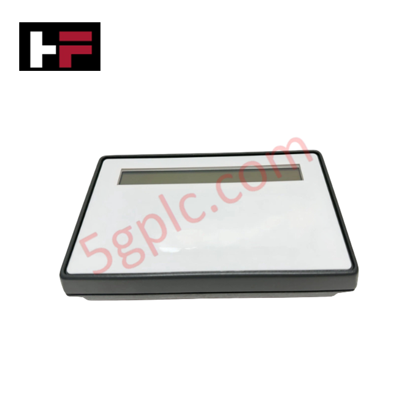
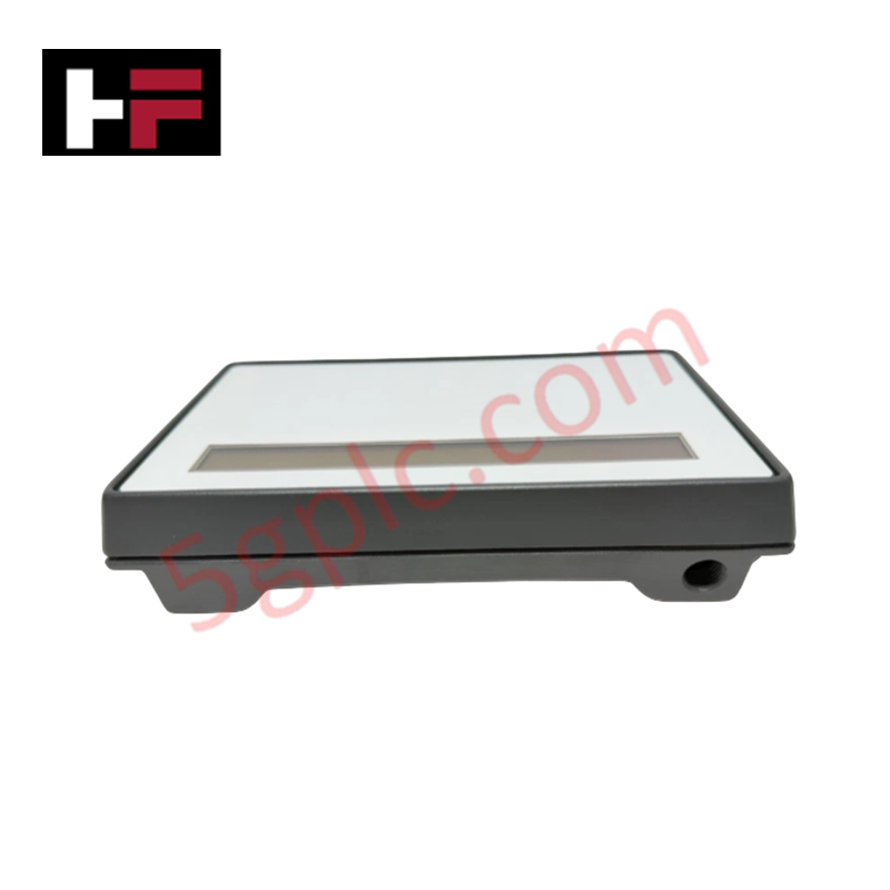
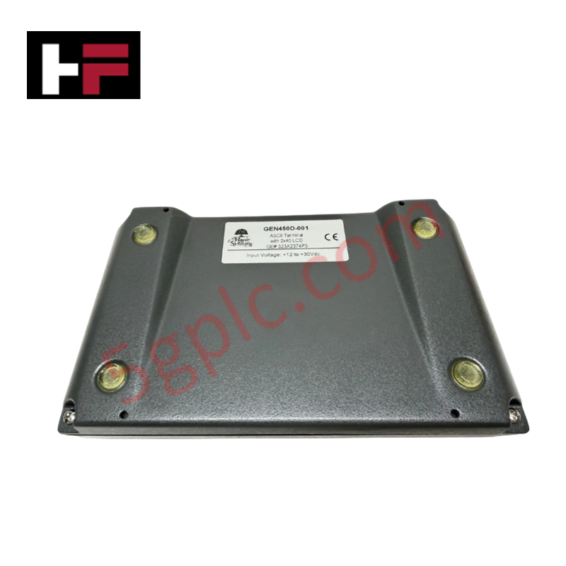
The GE 323A2374P3, also cataloged as the 323A2374P3 Mini-Terminal Control Display, operates as a dedicated hardware component for local operator interface and diagnostic alarm execution within GE Mark V Speedtronic platforms.
Hardware Specifications
| Parameter | Specification |
|---|---|
| Model | 323A2374P3 |
| Brand | GE / GE Drive Systems |
| Origin | USA |
| Operating Temp | -20 to +60 deg C |
| Power Consumption | Panel Interface Bus Powered (5 VDC / 24 VDC Control) |
| Display Type | 2-Line 40-Character LCD Panel |
| Input Interface | Membrane Keypad (20 Function Keys F1-F20 with Shift) |
| Dedicated Keys | ALARM SIL, ALARM ACK, ALARM RESET, Raise/Lower, Scroll |
| Mounting Type | Panel Mountable Screw Enclosure |
| Interface Port | Edge Connector Cable Assembly |
Backplane Bus Communication Velocity and Firmware Flash Compatibility
The 323A2374P3 translates front-panel membrane key presses into serial command frames transmitted over the Mark V internal interface bus. Onboard display drivers update the two-line alphanumeric LCD in real time to present system parameters and diagnostic fault alarms without degrading backplane bus communication velocity. Internal logic circuits maintain strict firmware flash compatibility across Mark V control rack nodes, providing rapid polling responses for local override actions, alarm silence, and alarm reset commands.
Frequently Asked Questions
Q: How are secondary key functions accessed on the 323A2374P3 front panel?
A: Secondary functions for keys F1 through F20 are activated by pressing and holding the designated shift key located in the bottom-left corner of the membrane keypad.
Q: How does the 323A2374P3 interface electrically with the main Mark V turbine control panel?
A: Electrical connection is established via a multi-pin wiring harness plugged directly into the dedicated connector port situated along one long edge of the display assembly.
Field Installation Guidelines
- Cut or verify the cutout dimensions on the switchgear cabinet door according to the Mark V panel mounting diagram.
- Insert the 323A2374P3 display assembly through the front panel cutout, ensuring the integrated bezel gasket sits flush against the metal door.
- Secure the module by tightening the panel mounting screws evenly around the enclosure frame.
- Route the multi-pin ribbon harness away from high-voltage AC lines and connect it securely to the display edge connector port.
- Connect an auxiliary cabinet earth ground strap to the metallic frame to prevent electrostatic discharge from interfering with the membrane keypad logic.
Additional Information
- 100% Genuine Parts: All products are original and authentic, ensuring reliable industrial performance.
- 30-Day Refund Guarantee: Return any in-stock item within 30 days in original, unopened packaging for a full refund (excluding shipping and fees).
- 12-Month Warranty: Covers defects in materials or workmanship; excludes misuse, normal wear, or unauthorized modifications.
- Worldwide Shipping: We ship via USPS, UPS, FedEx, and DHL. Delivery times vary by country and may be subject to customs or import fees.
- Support & Contact: Technical and warranty assistance is available anytime. Contact us here: Contact.
- Purchase Guidance: Check product specifications and compatibility carefully before ordering to ensure proper application.


Tech & Buying Guide

Understanding Marshalling Cabinets in Industrial Automation and Control Systems
Marshalling cabinets serve as the crucial connection hub between field instruments and centralized processing units. In large DCS and PLC control system architectures, hundreds of multipair field cables run from local junction boxes to the central instrument equipment room. The marshalling cabinet houses field terminal blocks, surge arresters, intrinsic safety isolation barriers, and interposing relays. By segregating field field-wiring terminations from sensitive processor hardware, engineers protect expensive controller backplanes from high-voltage transients. Consequently, this modular separation dramatically streamlines maintenance workflows and simplifies system expansion.

Essential Best Practices for PLC Wiring and Installation in Industrial Automation
Successful control system deployment begins with thoroughly reviewing manufacturer technical documentation. Controllers from major brands like Allen-Bradley, Siemens, and Schneider Electric feature unique terminal layouts. Engineers must verify voltage requirements before connecting power cables to prevent catastrophic equipment damage. Standard line connections require strict adherence to regional electrical codes and proper wire color coding. Furthermore, panel builders should always establish a robust low-impedance ground connection using at least 16-AWG copper conductor tied directly to the main plant grounding grid.

Demystifying Programmable Logic Controllers: Comprehensive Guide to PLC Classification and Selection in Industrial Automation
Modern industrial automation heavily relies on Programmable Logic Controllers (PLCs) to drive factory floor efficiency. Over my 15 years as an industrial automation expert working with DCS, TSI, and control systems, I have seen PLCs evolve into the central nervous system of modern manufacturing. Selecting the right controller requires a deep understanding of PLC types based on physical size, hardware architecture, and power supply configurations.