










Product Details
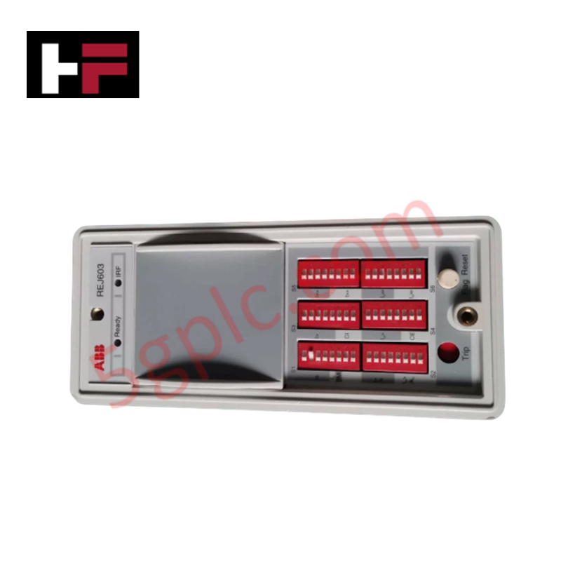
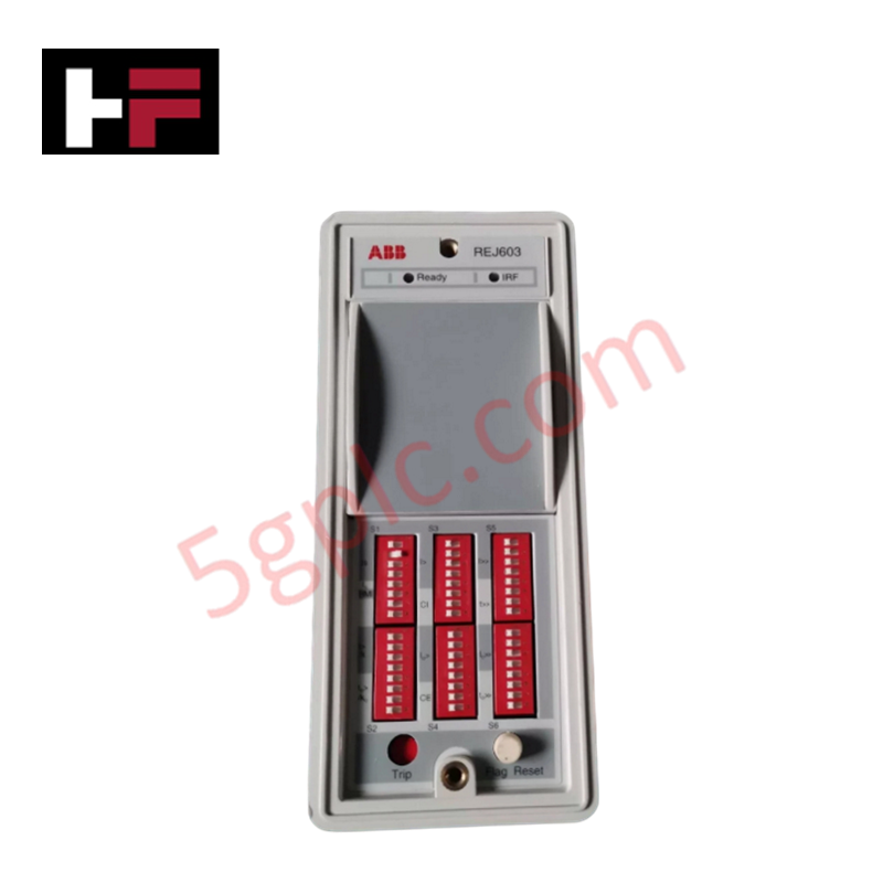
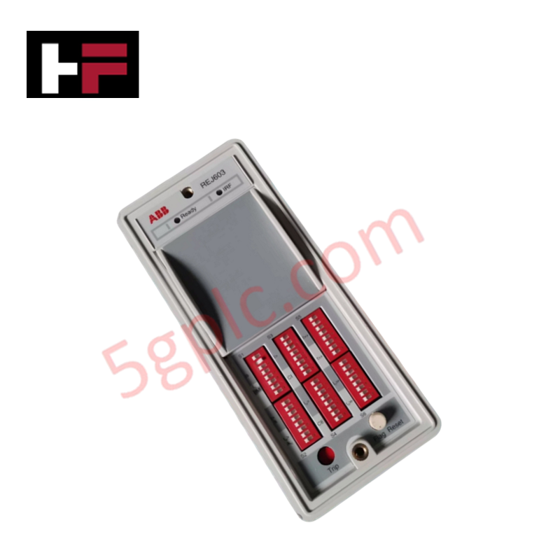
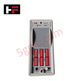
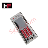
The ABB REJ603BBB10NN3XC, also cataloged as the REJ603 Self-Powered Feeder Protection Relay, operates as a dedicated hardware component for phase overcurrent, earth fault, and voltage monitoring tasks within Relion 600 secondary distribution platforms. Configured to function via direct loop power harvested from the main current transformers, the device triggers mechanical trip coils through dedicated binary output lines when electrical thresholds are exceeded.
Hardware Specifications
| Parameter | Specification |
|---|---|
| Model | REJ603BBB10NN3XC |
| Brand | ABB |
| Origin | India / Finland |
| Series | Relion 600 |
| Rated Frequency | 50/60 Hz |
| Rated Current | 1 A / 5 A (selectable) |
| Power Supply | Self-powered via CT input channels |
| Startup Power Requirement | 2.5 VA at rated current |
| Trip Output Channel | 1 NO (Normally Open) |
| Binary I/O Array | 1 Digital Input / 1 Digital Output (configurable) |
| Fault Recording Capacity | Up to 100 fault events stored in internal registers |
| User Interface Logic | LED indicators, DIP switch array |
| Communication Ports | None by default (optional serial interface available) |
| Configuration Method | Manual DIP switches or optional software parameterization |
| Enclosure Material | Flame-retardant plastic |
| Protection Rating | IP54 front, IP20 rear |
| Dimensions | 160 mm x 96 mm x 150 mm |
| Weight | 0.9 kg |
| Power Consumption | Derived from active CT input signals |
Backplane Bus Communication Velocity Licences Profile
The integration of this self-powered element into broader industrial arrangements requires matching specific hardware profiles to prevent bus degradation. Gating logic and trip execution are processed on local registers that maintain stable states regardless of backplane bus communication velocity licences constraints. The internal layout maps I/O density scaling options through manual DIP switches, ensuring absolute firmware flash compatibility with localized transformer safety interlocks and reducing hardware processing latency during severe phase faults.
Frequently Asked Questions
Q: What are the live removal restrictions for the REJ603BBB10NN3XC module?
A: Hot-swapping or unlatching the terminal block while the primary feeder is live is prohibited. Current transformer secondary connections must be short-circuited externally prior to physical decoupling to eliminate high inductive voltage generation.
Q: How does the device maintain configuration settings when the feeder line drops power?
A: Thresholds established via the hardware DIP switch matrix or saved to the non-volatile internal data storage remain preserved during line blackouts, requiring no active battery back-up path.
Q: What is the limitation regarding the startup power requirement?
A: The internal processing circuits require at least 2.5 VA of energy from the CT secondary line to initialize the protection routines and execute a valid binary trip command.
Field Installation Guidelines
- Current Transformer Terminals Pre-Check: Verify that all connection poles are tightly engaged and paired with matching 1 A or 5 A selectable terminals. Do not leave CT circuit runs loose during initial commissioning phases.
- Low-Voltage Signal Separation: Route the binary I/O signal lines separate from adjacent heavy AC phase bars. Keep terminal cable paths isolated inside designated, grounded wireways.
- Enclosure Earthing Continuity: Connect a low-impedance ground conductor from the rear IP20 frame screw directly to the copper master ground rail of the distribution cubicle.
Additional Information
- 100% Genuine Parts: All products are original and authentic, ensuring reliable industrial performance.
- 30-Day Refund Guarantee: Return any in-stock item within 30 days in original, unopened packaging for a full refund (excluding shipping and fees).
- 12-Month Warranty: Covers defects in materials or workmanship; excludes misuse, normal wear, or unauthorized modifications.
- Worldwide Shipping: We ship via USPS, UPS, FedEx, and DHL. Delivery times vary by country and may be subject to customs or import fees.
- Support & Contact: Technical and warranty assistance is available anytime. Contact us here: Contact.
- Purchase Guidance: Check product specifications and compatibility carefully before ordering to ensure proper application.









Tech & Buying Guide

Demystifying CPU Communication Ports in Siemens PLC Architectures
Industrial automation relies heavily on robust data exchange between devices. Without seamless connectivity, field instruments, network switches, human-machine interfaces, and programmable logic controllers cannot coordinate effectively. Therefore, understanding the various CPU communication ports available in Siemens hardware ensures efficient factory automation design and seamless system integration.

Mastering the Siemens PLC Scan Cycle: How the CPU Executes Automation Programs
Industrial automation relies heavily on programmable logic controllers (PLCs) to manage complex manufacturing processes. Many engineers dive straight into programming without mastering the underlying architecture. However, understanding how a PLC CPU executes a program ensures reliable system design. Therefore, mastering the scan cycle optimizes both performance and troubleshooting in modern control systems.

How to Connect to Siemens S7 PLCs: 5 Essential Communication Methods
Establishing a reliable hardware link between a programming terminal and a Siemens SIMATIC controller is essential for engineering workflows. Field engineers rely on distinct physical layers, ranging from legacy serial connections to high-speed Industrial Ethernet protocols. Modern factory automation environments prioritize fast data transfer and seamless driver integration. Selecting the correct connection method simplifies program downloads, online monitoring, and system troubleshooting in complex control systems.