


Product Details
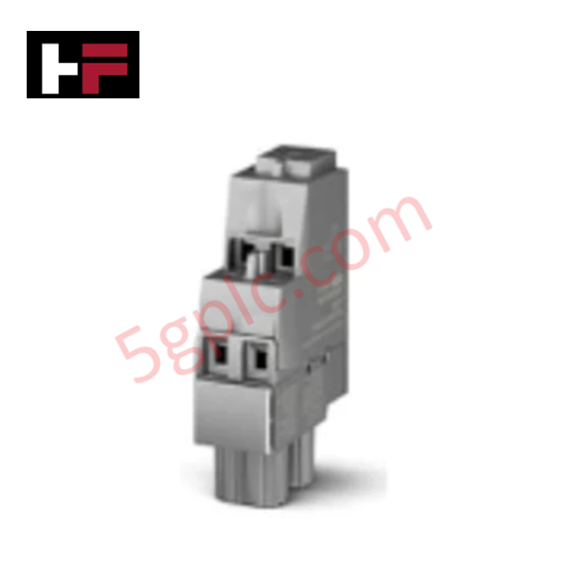
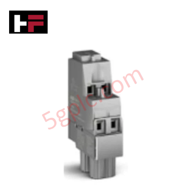
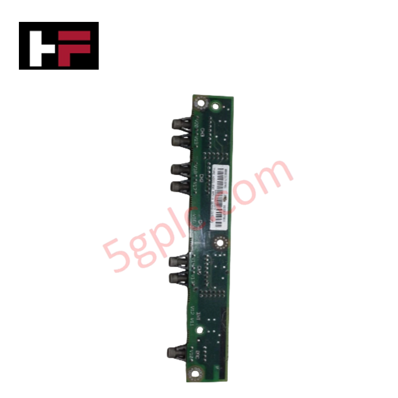
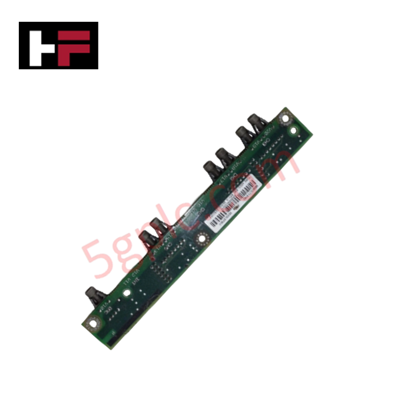
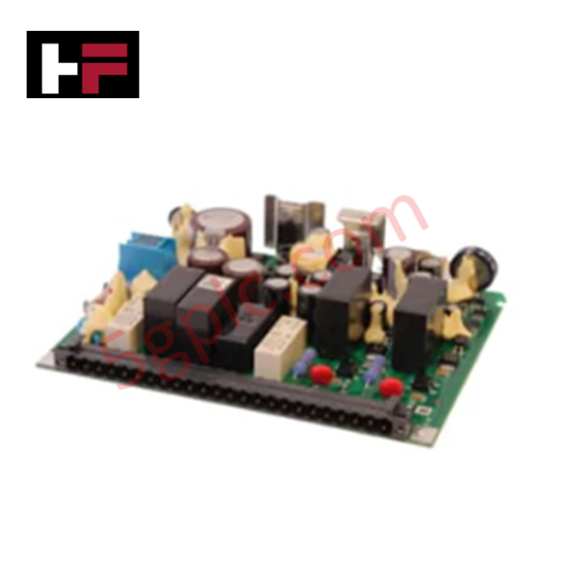
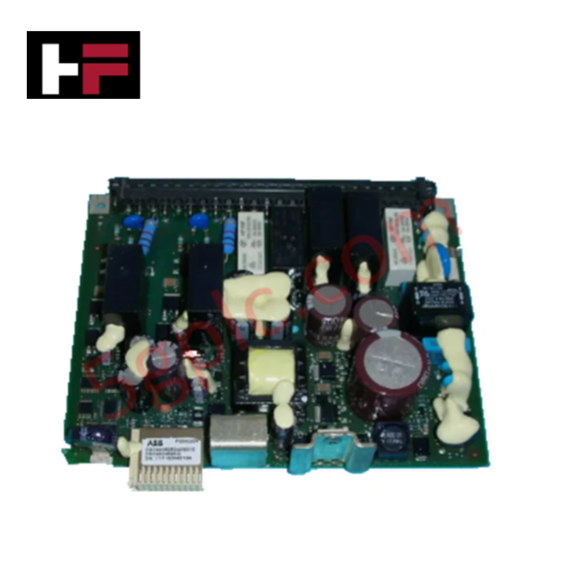
The ABB PTB810 3BSE080332R1, also cataloged as the PTB810 Power Injection Terminal Block, operates as a dedicated hardware component for 24 VDC field power delivery within S600/Select I/O module termination unit architectures.
Hardware Specifications
| Parameter | Specification |
|---|---|
| Model | PTB810 3BSE080332R1 (Article: 3BSE088182R1) |
| Brand | ABB |
| Origin | Sweden / Europe |
| Weight | Standard terminal block hardware allocation |
| Dimensions | Standard rail-mount module profile |
| Operating Temp | -40 to +70 deg C |
| Power Consumption | Passive distribution matrix (20 A maximum current capacity) |
| Voltage Input | 24 VDC nominal field power |
| Relative Humidity | 5% to 95% (non-condensing) |
| Altitude | -1000 to 5000 m |
| Pollution Degree | Pollution Degree 2 (IEC 60664-1) |
| Protection Class | IP20 (IEC 60529) |
Deterministic Network Routing and I/O Density Scaling
The ABB PTB810 3BSE080332R1 executes high-current electrical load balancing across neighboring Module Termination Units (MTUs) to permit uninhibited I/O density scaling routines. By driving up to 20 A of continuous field power locally, the hardware assembly stabilizes internal processing voltage levels for high-power Signal Conditioning Modules (SCMs). This direct power distribution circumvents tracking limits on backplane bus pathways, preventing mid-loop voltage attenuation while supporting consistent backplane bus communication velocity and total firmware flash compatibility across all networked local control assets.
Frequently Asked Questions
Q: What are the isolation and electrical constraints when using the four-screw power daisy-chain assembly?
A: The daisy-chain interconnect forms a common current distribution path. Total current across the terminal bridge must not exceed the maximum 20 A hardware rating to prevent localized thermal overload conditions.
Q: Can test probes be used while the 24 VDC current injection loop is actively powering the SCMs?
A: Yes. The integrated test probe holes permit standard industrial diagnostic multimeter connection during live operational runtime without causing loop circuit breaks or electrical disruptions to the module termination unit.
Field Installation Guidelines
- Snaps the IP20 terminal housing securely onto a standard symmetrical mounting rail alongside the associated module termination unit cluster.
- Terminate the 24 VDC field power lines into the secure clamping screws, validating that all torque values conform to industrial standards.
- Utilize the dedicated four-screw terminal infrastructure when daisy-chaining multiple power supply inputs across contiguous hardware segments.
- Keep adequate space from adjacent high-voltage heat sources to sustain the complete -40 to +70 deg C environmental operational profile.
Additional Information
- 100% Genuine Parts: All products are original and authentic, ensuring reliable industrial performance.
- 30-Day Refund Guarantee: Return any in-stock item within 30 days in original, unopened packaging for a full refund (excluding shipping and fees).
- 12-Month Warranty: Covers defects in materials or workmanship; excludes misuse, normal wear, or unauthorized modifications.
- Worldwide Shipping: We ship via USPS, UPS, FedEx, and DHL. Delivery times vary by country and may be subject to customs or import fees.
- Support & Contact: Technical and warranty assistance is available anytime. Contact us here: Contact.
- Purchase Guidance: Check product specifications and compatibility carefully before ordering to ensure proper application.
Tech & Buying Guide

Industrial PC vs. Commercial PC: Selecting the Right Hardware for Automation
In the demanding world of factory automation, selecting the correct computing platform is critical for system reliability. While commercial PCs power our daily lives, they often fail when subjected to the harsh realities of the production floor. Understanding the fundamental differences between an Industrial PC (IPC) and a standard office PC helps engineers optimize control systems for longevity and performance.

Core Components of Programmable Logic Controllers (PLC) in Industrial Automation
A Programmable Logic Controller (PLC) serves as the digital backbone of modern factory automation. Whether you are managing complex assembly lines or simple process loops, understanding the hardware and software architecture of a PLC is essential for any control systems engineer.

PLC vs. PC: Navigating the Architectural Differences in Industrial Automation
In the realm of factory automation, professionals often debate the roles of Programmable Logic Controllers (PLCs) and Personal Computers (PCs). While both devices share fundamental computing architectures—including a processor, memory, and an operating system—their design philosophies diverge significantly. Understanding these distinctions is critical for selecting the right hardware for your industrial control systems.