


Product Details
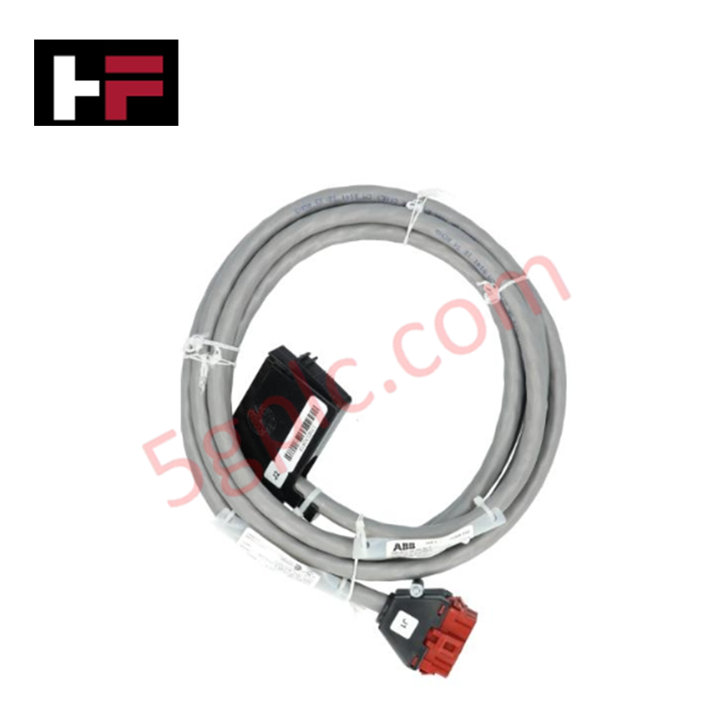
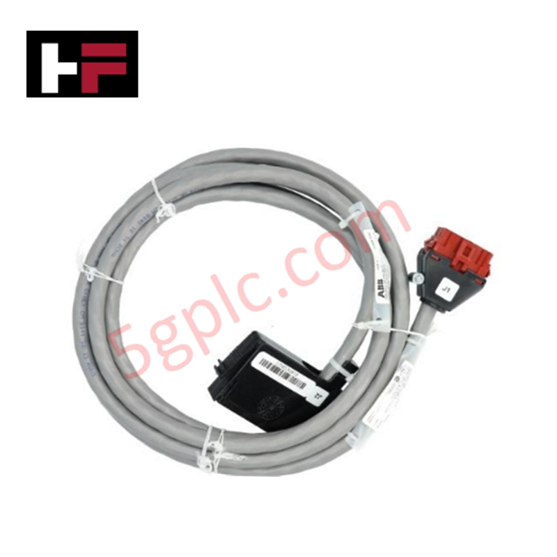
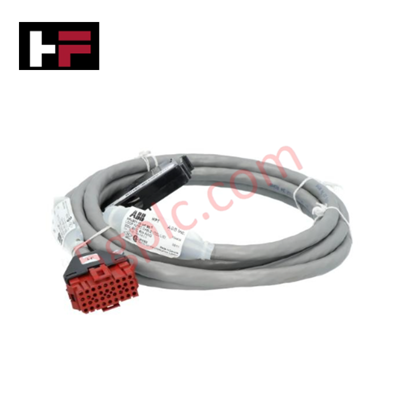
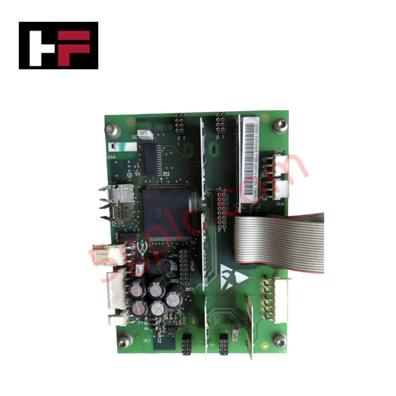
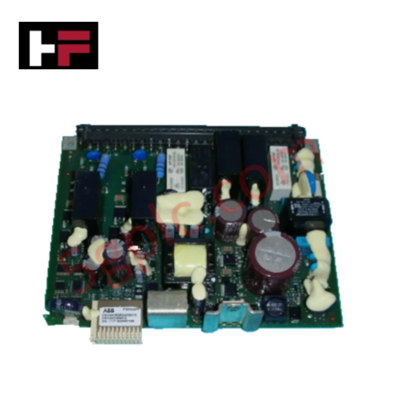
The ABB NKLM01-10, also cataloged as the NKLM01 Network Interface Cable, operates as a dedicated hardware component for high-performance data transmission within ABB Bailey INFI 90 and Symphony platforms.
Hardware Specifications
| Parameter | Specification |
|---|---|
| Model | NKLM01-10 |
| Brand | ABB |
| Origin | USA / Europe standard sourcing |
| Weight | 1.25 lbs |
| Dimensions | 10 ft (3.05 m) length |
| Operating Temp | -20 to +70 deg C |
| Power Consumption | Passive physical media communication loop |
| Rated Voltage | 300 V |
| Connector Types | Industrial-grade RJ and D-sub interfaces |
| Shielding | Combined braided and foil shielding |
| Jacket Material | PVC |
| Flame Retardancy | UL 94 V-0 |
| Operating Humidity | 5% to 95% (non-condensing) |
| Storage Temp | -40 to +85 deg C |
Deterministic Network Routing and I/O Density Scaling
The ABB NKLM01-10 functions as a deterministic physical layer linkage connecting Symphony processors and peripheral network interface nodes. The dual-layer braided and foil shield infrastructure enforces high-velocity backplane bus communication velocity across data paths, maintaining fixed line impedance under continuous signal loading. This specialized shielding matrix establishes direct cross-talk containment between parallel high-density digital channels, allowing maximum I/O density scaling routines across nearby DIN rail chassis without risking packet drops, transmission retries, or firmware flash compatibility faults at the controller interface.
Frequently Asked Questions
Q: What are the installation restrictions regarding hot-swapping or un-mating the D-sub and RJ connectors during active runtime communication?
A: This cable is a passive medium; however, uncoupling the connector assemblies while data frames are running will immediately break the deterministic network token loop, generating communication network faults in the master controller diagnostic buffer.
Q: How does the grounding schema of the combined braided and foil shielding layout interface with the system chassis?
A: Grounding continuity is managed directly through the metal shells of the industrial-grade connectors. The shield assembly links to the master rack framework automatically upon full seating and mechanical latching of the interface hardware.
Field Installation Guidelines
- Route the assembly along dedicated low-voltage instrumentation trays, maintaining physical isolation boundaries from high-voltage motor supply runs or inductive loads.
- Verify that the routing radius does not exceed the structural minimum bending tolerances of the PVC outer layer to prevent foil deformation.
- Align the industrial D-sub termination pins with the mating plug before tightening the retention hardware to standard locking limits.
- Clean the interface contacts of any particulate contamination before final engagement to secure continuity across the synchronous network line.
Additional Information
- 100% Genuine Parts: All products are original and authentic, ensuring reliable industrial performance.
- 30-Day Refund Guarantee: Return any in-stock item within 30 days in original, unopened packaging for a full refund (excluding shipping and fees).
- 12-Month Warranty: Covers defects in materials or workmanship; excludes misuse, normal wear, or unauthorized modifications.
- Worldwide Shipping: We ship via USPS, UPS, FedEx, and DHL. Delivery times vary by country and may be subject to customs or import fees.
- Support & Contact: Technical and warranty assistance is available anytime. Contact us here: Contact.
- Purchase Guidance: Check product specifications and compatibility carefully before ordering to ensure proper application.
Tech & Buying Guide

Industrial PC vs. Commercial PC: Selecting the Right Hardware for Automation
In the demanding world of factory automation, selecting the correct computing platform is critical for system reliability. While commercial PCs power our daily lives, they often fail when subjected to the harsh realities of the production floor. Understanding the fundamental differences between an Industrial PC (IPC) and a standard office PC helps engineers optimize control systems for longevity and performance.

Core Components of Programmable Logic Controllers (PLC) in Industrial Automation
A Programmable Logic Controller (PLC) serves as the digital backbone of modern factory automation. Whether you are managing complex assembly lines or simple process loops, understanding the hardware and software architecture of a PLC is essential for any control systems engineer.

PLC vs. PC: Navigating the Architectural Differences in Industrial Automation
In the realm of factory automation, professionals often debate the roles of Programmable Logic Controllers (PLCs) and Personal Computers (PCs). While both devices share fundamental computing architectures—including a processor, memory, and an operating system—their design philosophies diverge significantly. Understanding these distinctions is critical for selecting the right hardware for your industrial control systems.