


Product Details
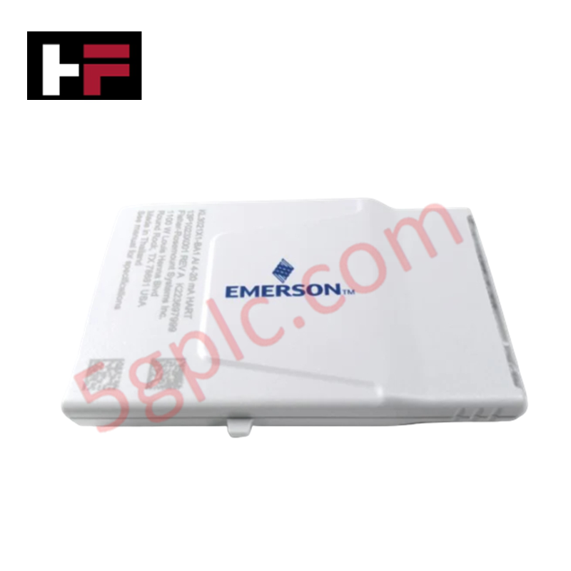
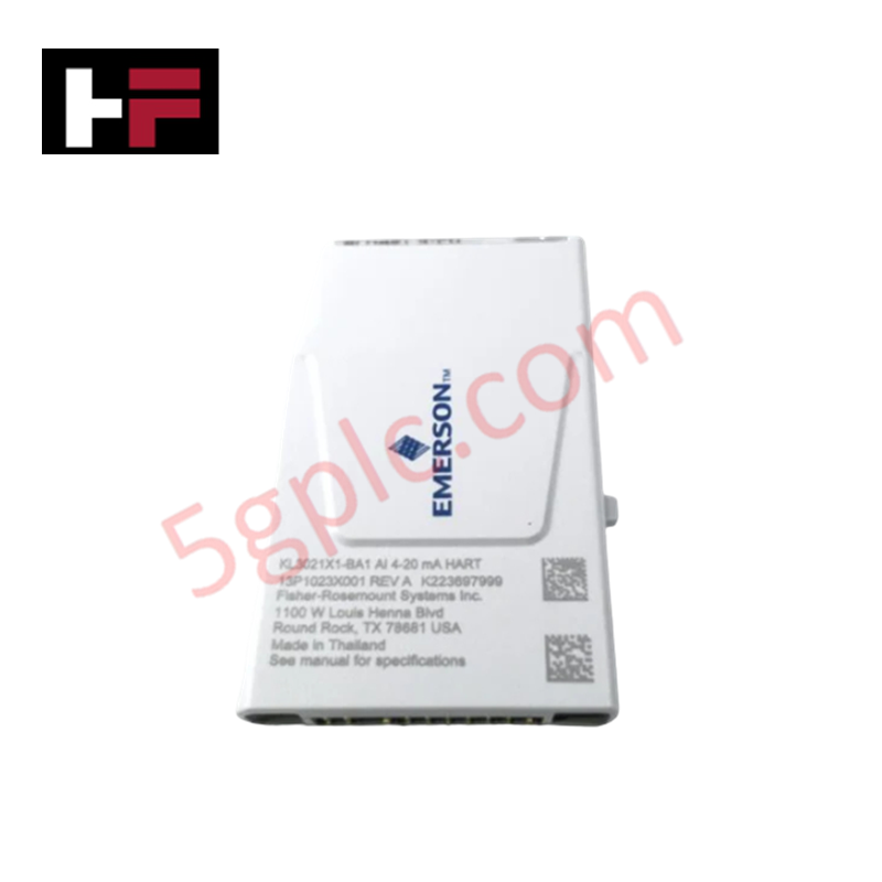
Configured for high-side switching in CHARM I/O subsystems, the Emerson KL3002X1-BA1 (KL3002X1-BA1 Discrete Output Module) provides direct physical execution of 24 VDC output control signals across distributed I/O architectures.
Hardware Specifications
| Parameter | Specification |
|---|---|
| Model | KL3002X1-BA1 |
| Brand | Emerson |
| Origin | Subject to factory shipping documentation |
| Weight | Subject to standard CHARM unit weight |
| Dimensions | Standard CHARM form factor |
| Operating Temp | -40 deg C to 70 deg C |
| Power Consumption | 6.3 VDC at 32 mA (Bus); 24 VDC at 5 mA (Field) |
| Output Type | Digital Output (High Side) |
| Output Voltage | 24 VDC |
4-20 mA HART Loop Protocol Connectivity
While the KL3002X1-BA1 is a discrete output module, its integration within the Emerson CHARM I/O Subsystem often occurs in environments where 4-20 mA HART loop protocol connectivity is present on adjacent channels. The module's design allows for per-channel flexibility, enabling localized high-side switching near the field device. This decentralized approach reduces field wiring requirements and simplifies loop-level troubleshooting by isolating discrete control outputs from the shared carrier backplane. The module maintains signal integrity through internal current limiting and voltage regulation, ensuring that discrete switching operations do not introduce common-mode noise to sensitive analog measurement loops on the same carrier.
Frequently Asked Questions
Q: Does the KL3002X1-BA1 support hot-swapping during normal system operation?
A: Yes. The CHARM I/O Subsystem is designed to allow individual modules to be removed or replaced while the system is energized, provided the carrier interface is rated for the specific hazardous area classification.
Q: Is this module compatible with standard inductive loads?
A: The module is designed for 24 VDC high-side switching. When controlling inductive loads such as solenoid valves or relays, ensure an external flyback diode is installed to suppress inductive kickback, as excessive voltage spikes can exceed the internal semiconductor ratings.
Field Installation Guidelines
- Carrier Insertion: Align the module with the designated CHARM carrier slot. Ensure the module is seated fully and the latching mechanism is secured to maintain a reliable connection to the CHARM bus.
- Field Wiring: Connect the field output device to the terminal block associated with the module. Maintain proper polarity for 24 VDC switching circuits to prevent damage to the output driver stage.
- Hazardous Area Requirements: For Zone 2 and Class I Div. 2 applications, ensure the module is installed within an appropriately rated enclosure and that all wiring methods comply with local codes for hazardous location electrical installations.
- Environmental Considerations: Although rated for -40 deg C to 70 deg C, maintain adequate clearance around the carrier for thermal dissipation to ensure long-term stability of the switching electronics.
- Validation: After installation, verify the output state by manually forcing the discrete output via the control software to confirm proper actuation of the field device.
Additional Information
- 100% Genuine Parts: All products are original and authentic, ensuring reliable industrial performance.
- 30-Day Refund Guarantee: Return any in-stock item within 30 days in original, unopened packaging for a full refund (excluding shipping and fees).
- 12-Month Warranty: Covers defects in materials or workmanship; excludes misuse, normal wear, or unauthorized modifications.
- Worldwide Shipping: We ship via USPS, UPS, FedEx, and DHL. Delivery times vary by country and may be subject to customs or import fees.
- Support & Contact: Technical and warranty assistance is available anytime. Contact us here: Contact.
- Purchase Guidance: Check product specifications and compatibility carefully before ordering to ensure proper application.

Tech & Buying Guide
PLC vs. PAC: Navigating Selection in Modern Industrial Automation
Selecting the right controller is a fundamental decision in industrial automation. While the lines between Programmable Logic Controllers (PLC) and Programmable Automation Controllers (PAC) often blur, understanding their core architectural differences is essential for system reliability. Both controllers serve as the brain of control systems, yet their specific capabilities dictate their suitability for various factory automation tasks.
Transforming Textile Manufacturing: The Strategic Integration of Industrial Automation and AI
The textile industry stands at a critical technological crossroads. Legacy operations must now embrace digital transformation to remain competitive in a global market. By integrating advanced industrial automation—ranging from PLC-controlled machinery to sophisticated AI-driven analytics—manufacturers can significantly boost productivity, minimize material waste, and elevate overall product quality.

Navigating Industrial Communication Protocols: A Technical Guide for Modern PLCs
In the realm of industrial automation, the Programmable Logic Controller (PLC) serves as the brain of the factory floor. However, its true power is unlocked through robust communication protocols. These digital pathways ensure seamless data exchange between controllers, sensors, and enterprise-level management systems.