


Product Details
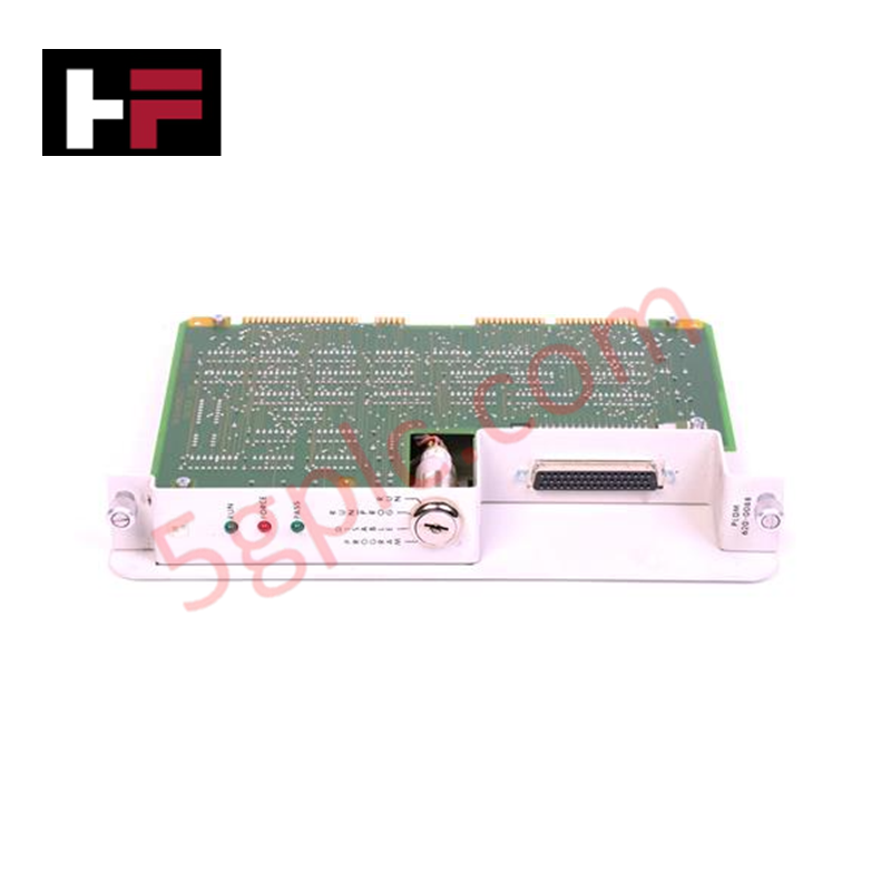
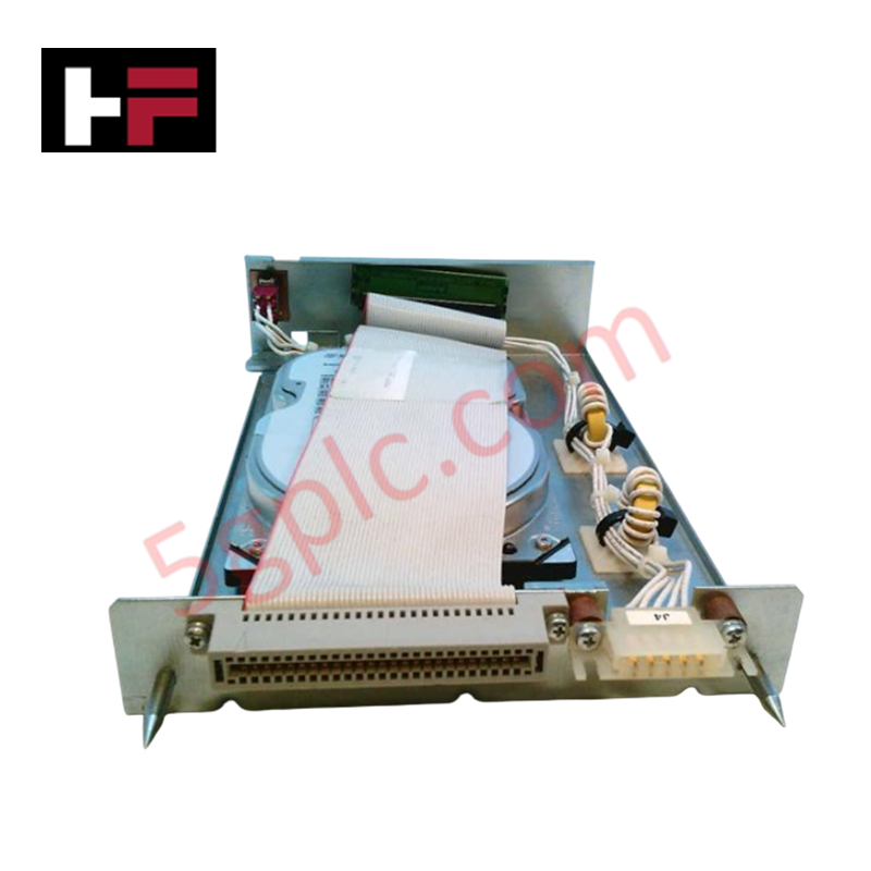
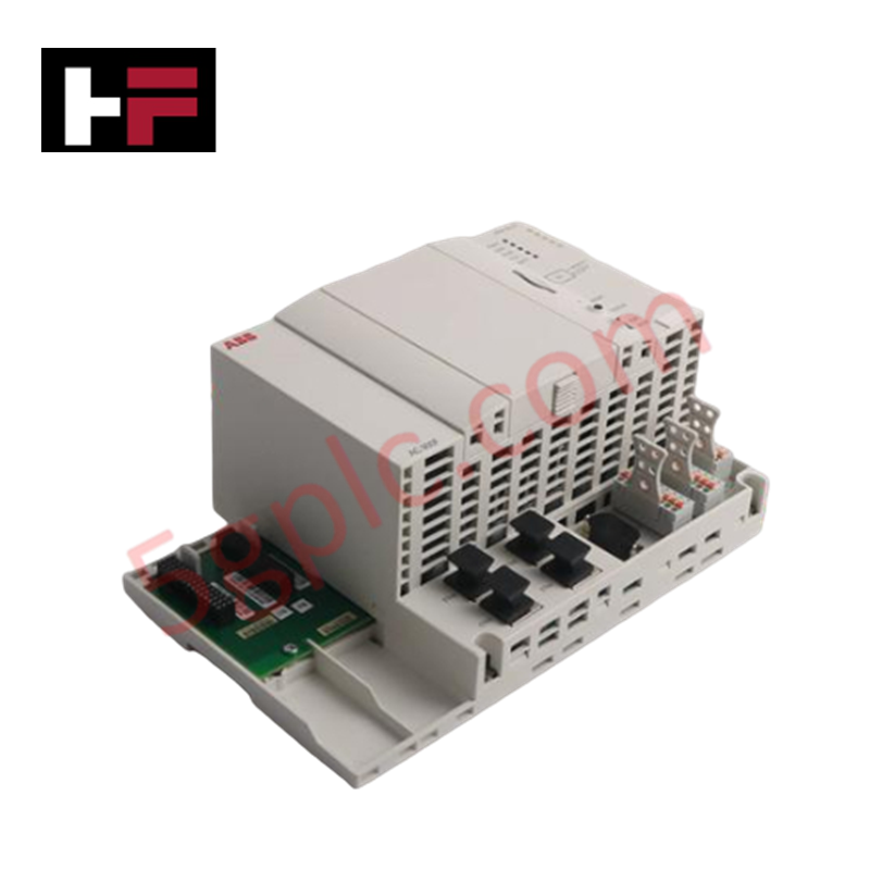
Configured for signal distribution and communication management in IPC 620 control systems, the Honeywell 620-0088 (620-0088 Parallel Link Drive Module) provides direct physical execution of data routing across the system backplane. This module operates as the primary interface for managing deterministic communication links, ensuring data synchronization between the industrial microcomputer and connected I/O racks.
Hardware Specifications
| Parameter | Specification |
|---|---|
| Model | 620-0088 |
| Brand | Honeywell |
| Origin | USA |
| Weight | 0.63 kg (1.39 lbs) |
| Dimensions | Not specified |
| Operating Temp | Standard industrial ambient range |
| Power Consumption | Backplane dependent |
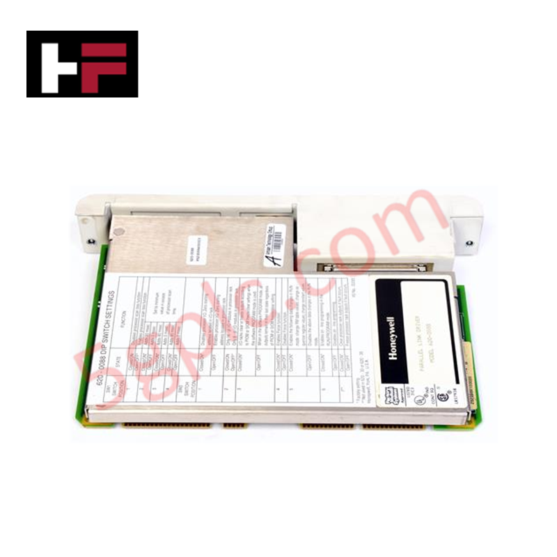
| Configuration | 2 DIP switches; key slot interface |
Backplane Bus Communication and Deterministic Networks
The 620-0088 module manages backplane bus communication velocity to maintain real-time data integrity within the IPC 620 architecture. The module utilizes onboard DIP switches for hard-coded address configuration, allowing for deterministic network node identification. Proper firmware flash compatibility is required when upgrading the module within a multi-rack system; technicians must ensure that the master controller’s I/O scanning frequency is synchronized with the link driver to prevent communication timeouts or packet collisions. In environments with high electrical noise, shielding integrity for the parallel link bus is necessary to maintain signal stability across the extended I/O bus topology.
Frequently Asked Questions
Q: Are the DIP switches hot-swappable for configuration changes?
A: No. DIP switch adjustments must be performed while the module is powered down and removed from the rack to prevent configuration errors or backplane communication conflicts.
Q: How is node addressing managed on the 620-0088?
A: Node addressing is defined by the 2 onboard DIP switches. These must be configured in accordance with the specific backplane slot position and the overall system communication map defined in the controller software.
Field Installation Guidelines
- Mounting: Align the module with the dedicated rack slot using the keyed slot mechanism to ensure correct pin alignment. Do not force the module into the backplane, as this may damage the bus interface pins.
- Grounding: Ensure the rack itself is properly earth-grounded. The module relies on the backplane for reference ground; poor chassis grounding can introduce noise into the parallel link signals.
- Bus Termination: Verify that the final rack in the communication loop is correctly terminated. Improper termination will cause signal reflections, resulting in intermittent link drops.
- Wiring: Maintain a minimum distance of 30 cm from high-voltage AC cabling to prevent inductive coupling into the parallel link signals.
Additional Information
- 100% Genuine Parts: All products are original and authentic, ensuring reliable industrial performance.
- 30-Day Refund Guarantee: Return any in-stock item within 30 days in original, unopened packaging for a full refund (excluding shipping and fees).
- 12-Month Warranty: Covers defects in materials or workmanship; excludes misuse, normal wear, or unauthorized modifications.
- Worldwide Shipping: We ship via USPS, UPS, FedEx, and DHL. Delivery times vary by country and may be subject to customs or import fees.
- Support & Contact: Technical and warranty assistance is available anytime. Contact us here: Contact.
- Purchase Guidance: Check product specifications and compatibility carefully before ordering to ensure proper application.

Tech & Buying Guide

Redundant Automation Systems: Ensuring Continuous Uptime in Critical Control Infrastructure
System reliability directly determines operational profitability across high stakes process industries. Modern industrial automation platforms must eliminate single points of failure to prevent catastrophic shutdowns. Deploying fault tolerant architecture safeguards complex facilities against unexpected hardware glitches, network disruptions, and maintenance outages.

Understanding Types of Noise in Electronic Circuits and Control Systems
Signal integrity directly determines measurement accuracy and loop stability across industrial automation environments. Electronic noise introduces unwanted stochastic interference into analog loops, sensor feedback lines, and digital fieldbus networks. Understanding how intrinsic electronic noise and external electromagnetic interference manifest allows control engineers to optimize signal conditioning and shield sensitive instrumentation effectively.

Why 24V DC Power Supplies Standardize Modern Industrial Automation
Industrial control cabinets worldwide rely on 24V DC as the universal power standard for field instrumentation, sensors, and controllers. Walk into any manufacturing plant, and you will find PLCs, human-machine interfaces (HMIs), and smart actuators running on extra-low voltage DC. Standardizing on 24V DC enhances operational safety, lowers cabinet footprint, and maintains steady control performance across factory networks.