










Product Details
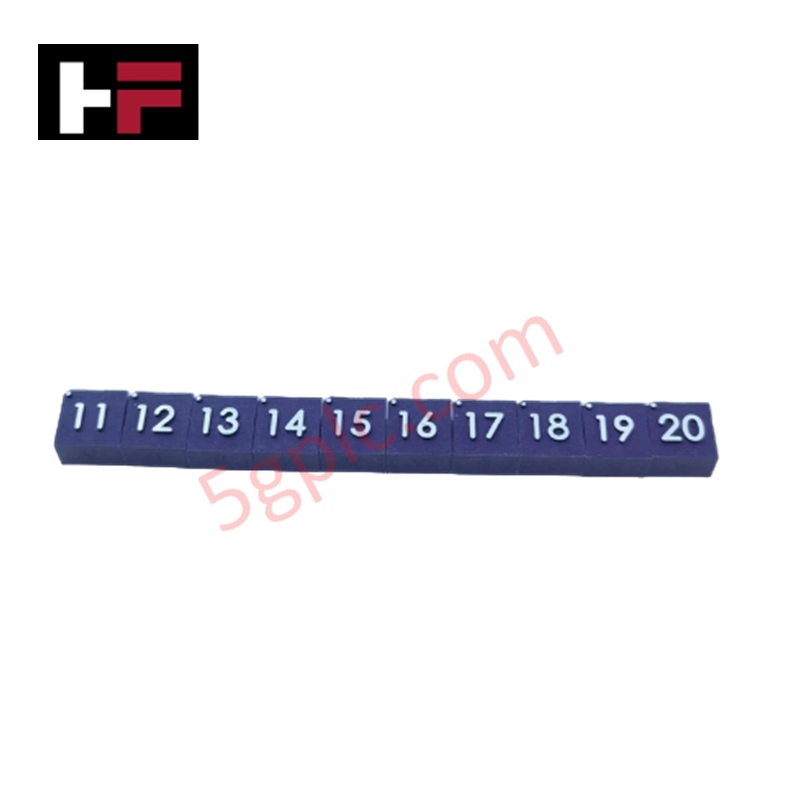
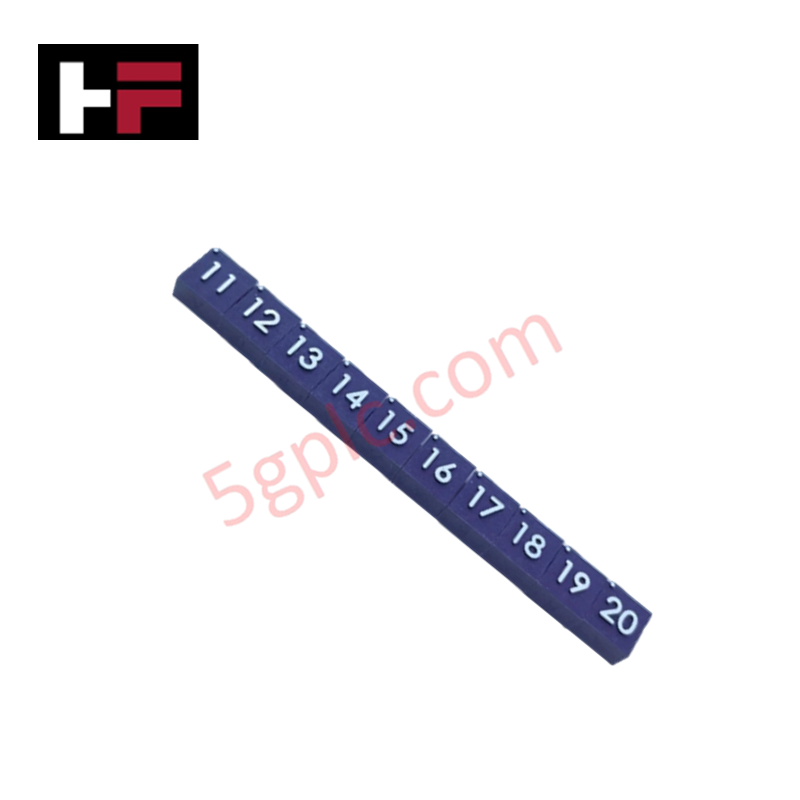
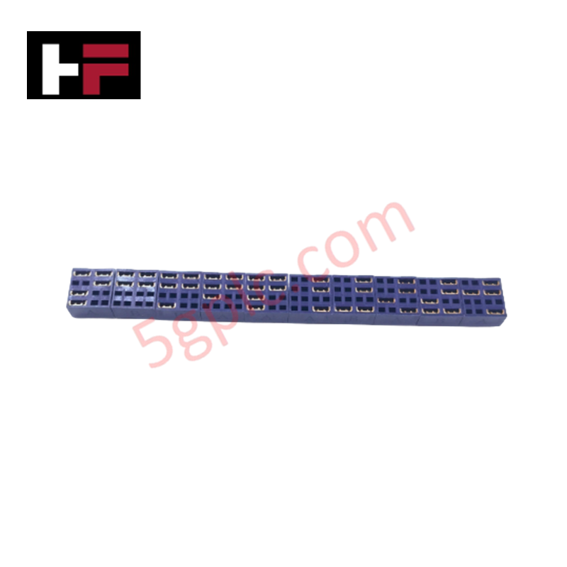
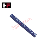
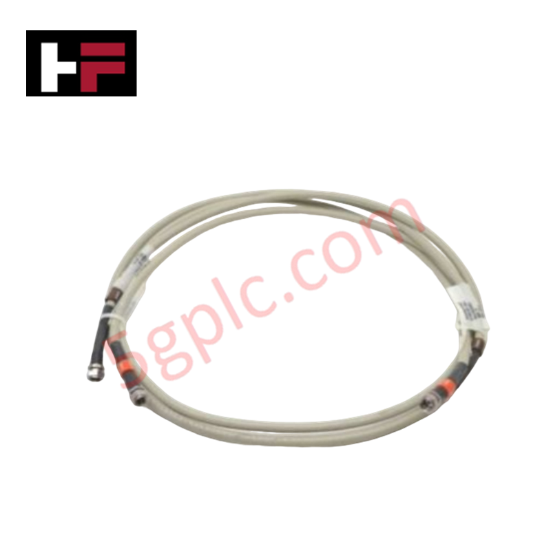
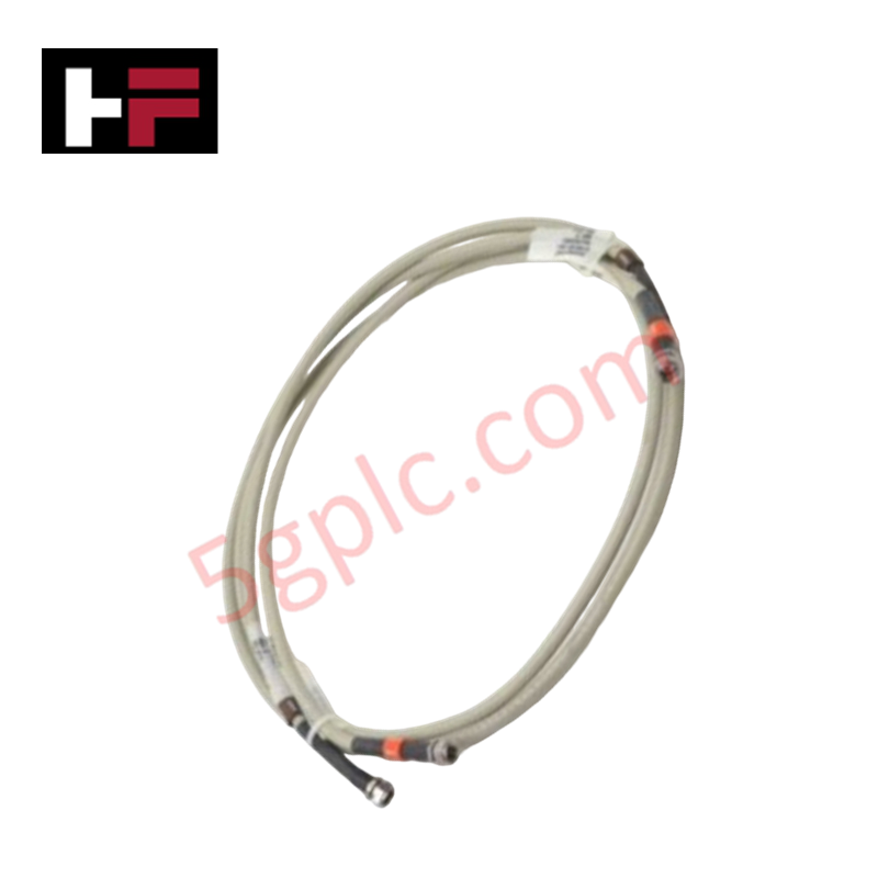
The Honeywell 51153818-102, also cataloged as the 51153818-102 Jumper Kit, operates as a dedicated hardware component for specific circuit routing configuration within Honeywell Experion PKS C300 Controller and HPMM module platforms. The hardware kit provides manual physical configuration links across the system carrier boards to bridge designated signal pathways or hardware tracking circuits.
Hardware Specifications
| Parameter | Specification |
|---|---|
| Model | 51153818-102 |
| Brand | Honeywell |
| Series / Module Type | Experion PKS / Jumper Kit |
| Origin | USA |
| Weight | 0.2 kg |
| Dimensions | 3.5 cm x 4 cm x 4.5 cm |
| Operating Temp | -40 to +70 deg C (Standard backplane internal ambient) |
| Power Consumption | Passive hardware element (0 W) |
| Jumper Type | Violet jumpers 11-20 |
| Compatibility | Honeywell C300 Controllers and HPMM Modules |
Channel-to-Channel Isolation and Loop Configuration
The placement of the 51195156-300 or related jumper sets within the Honeywell terminal board architecture directly determines internal circuit mapping. In multi-channel analog schemes, positioning these low-resistance jumper links allows configuration of channel-to-channel isolation parameters by defining shared ground returns or separate reference links. Proper alignment ensures no physical cross-talk develops between high-frequency digital lines and neighboring analog circuits running the 4-20 mA HART loop protocol, preserving signal boundary definition across the I/O rack.
Frequently Asked Questions
Q: Can the 51153818-102 jumpers be adjusted while the C300 controller or HPMM module is powered and running active loops?
A: No. Altering manual jumper links under live system power changes the internal electrical routing instantly. This can cause channel voltage transients, interrupt active process monitoring, or trigger unexpected fail-safe state activations on associated modules.
Q: Do these jumpers affect the impedance values of the system backplane channels?
A: The solid copper pins inside the violet jumpers are engineered to provide negligible insertion resistance, ensuring that correct circuit connectivity is established without altering the base trace impedance or degrading signal propagation.
Field Installation Guidelines
- System Power De-energization: Disconnect power from the controller terminal assembly or module baseboard before handling the jumper pins to prevent electrical shorting during configuration changes.
- Jumper Pin Alignment: Verify the alignment of the violet jumper housing over the intended terminal pins (channels 11 through 20). Press the component straight down onto the pins to ensure full mechanical and electrical contact.
- Shield Inspection: Ensure that the jumper installation does not interfere with external cable shielding loops or touch adjacent grounding bars inside the panel housing.
- Environmental Cleanliness: Clean the target pinning matrix of any dust or oxidation before inserting the new jumpers to prevent high-contact resistance from impacting the accuracy of low-voltage measurement circuits.
Additional Information
- 100% Genuine Parts: All products are original and authentic, ensuring reliable industrial performance.
- 30-Day Refund Guarantee: Return any in-stock item within 30 days in original, unopened packaging for a full refund (excluding shipping and fees).
- 12-Month Warranty: Covers defects in materials or workmanship; excludes misuse, normal wear, or unauthorized modifications.
- Worldwide Shipping: We ship via USPS, UPS, FedEx, and DHL. Delivery times vary by country and may be subject to customs or import fees.
- Support & Contact: Technical and warranty assistance is available anytime. Contact us here: Contact.
- Purchase Guidance: Check product specifications and compatibility carefully before ordering to ensure proper application.
Tech & Buying Guide

Executing a PLC System Site Acceptance Test (SAT): The Definitive Engineering Guide
The transition of a Programmable Logic Controller (PLC) cabinet from a controlled factory floor to a volatile plant environment represents a critical milestone in factory automation. While a Factory Acceptance Test (FAT) validates standalone hardware compliance under ideal conditions, it cannot replicate real-world process dynamics. Therefore, deploying an industrial automation system requires a rigorous Site Acceptance Test (SAT) to verify total loop integrity, field wiring wiring metrics, and process control parameters before final customer handover.

Advanced Integration: Master Protocol for VFD Commissioning and Testing
Deploying variable frequency drives (VFDs) requires precise execution during the initial commissioning phase. Junior automation engineers often find the first power-up sequence intimidating. However, following a rigorous engineering framework ensures equipment safety and system reliability. Proper startup procedures protect both the drive electronics and the connected motor.

Optimizing Factory Automation: The Definitive Guide to VFD Preventive Maintenance
Variable Frequency Drives (VFDs) serve as critical assets in modern industrial automation. These power electronic devices regulate electric motors by adjusting the supplied frequency and voltage. Consequently, industries utilize VFDs to reduce energy consumption and optimize process control. Major manufacturers like Siemens, ABB, and Yaskawa design highly efficient drives. However, sustained efficiency requires a rigorous preventive maintenance program.