


Product Details
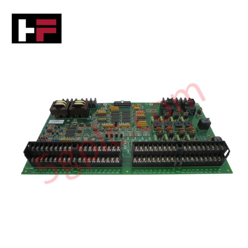
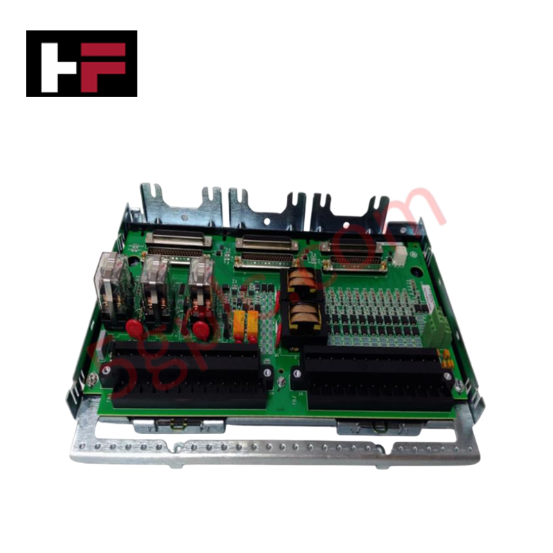
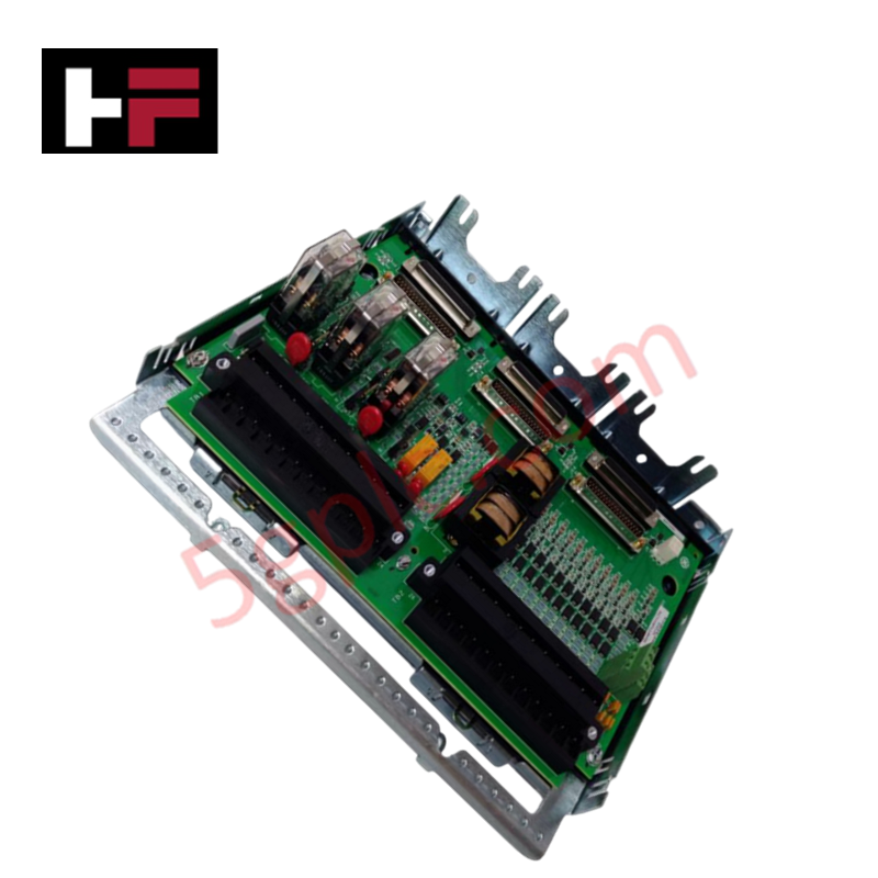
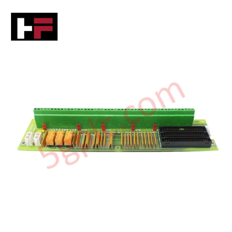
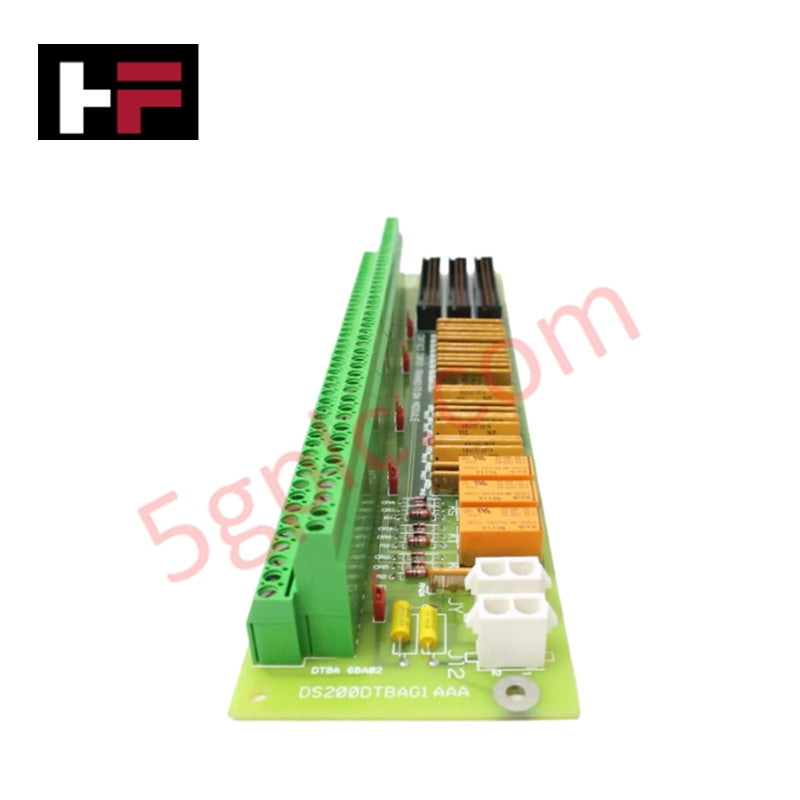
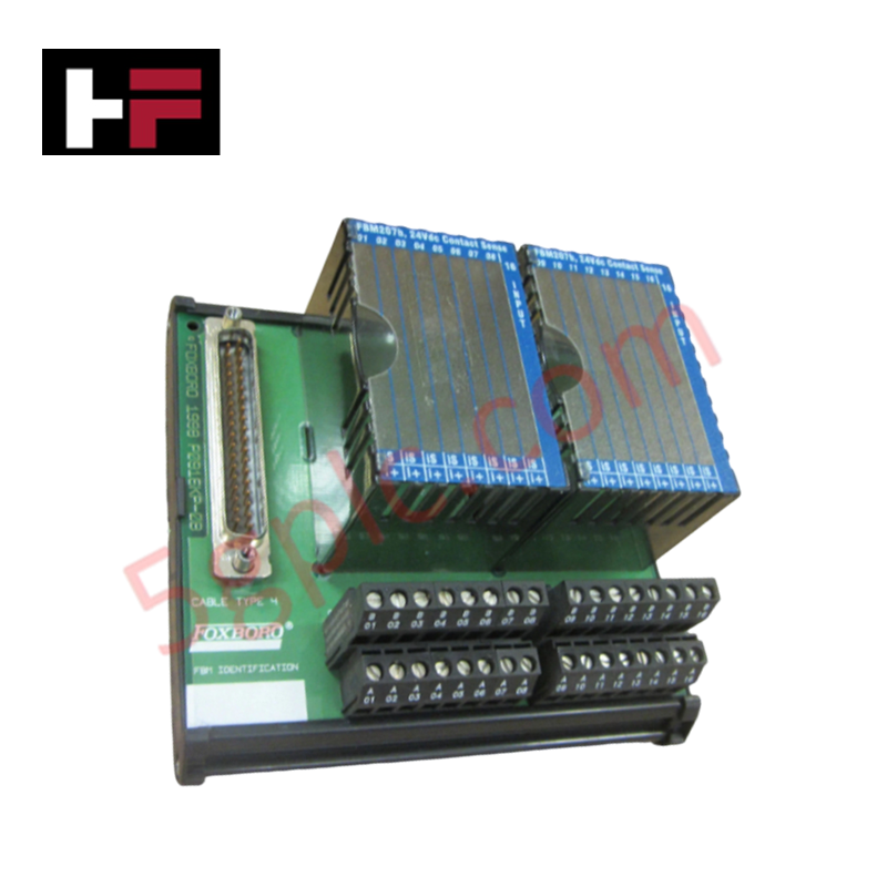
The General Electric DS200DDTBG2A, also cataloged as the DS200DDTB LCI Auxiliary I/O Terminal Board, operates as a dedicated hardware component for high-voltage signal conditioning and interface distribution within Mark V LM Speedtronic turbine control platforms.
Hardware Specifications
| Parameter | Specification |
|---|---|
| Model | DS200DDTBG2A |
| Brand | General Electric |
| Origin | USA |
| Dimensions | Panel/rack-mounted form factor |
| Operating Temp | -20 deg C to +60 deg C |
| Power Consumption | Derived from ADMA module |
| Voltage Range | 14 V dc to 32 V dc |
| I/O Channels | 12 total |
Industrial Control and Firmware Compatibility
The DS200DDTBG2A requires backplane bus communication velocity settings compatible with the Mark V LM rack architecture. Firmware flash compatibility is managed through the interconnected DS200ADMA daughterboard, which interfaces with the DSPC processor. The board supports I/O density scaling by allowing multiple high-voltage and current-sensing signals to be multiplexed into the DSP control loops. Deterministic network performance is maintained as the DDTB provides the necessary scaling and buffering for the DSP to execute real-time control algorithms. Ensure all terminal board jumpers and configuration settings are verified against the specific turbine control system logic.
Frequently Asked Questions
Q: Can the 4-20 mA current output and voltage output be used simultaneously?
A: Yes. The board supports both output types actively. They can be used individually or simultaneously by connecting to the respective screw terminals provided for each output type.
Q: What is the isolation rating for the high-voltage AC inputs?
A: The high-voltage AC inputs use isolated step-down transformers and passive filtering. The screw terminal blocks and internal circuit paths are rated and isolated for 1000 V peak transients.
Q: How is the board powered in the LCI system?
A: Power is supplied to the DS200DDTBG2A via the DS200ADMA analog-to-digital module daughterboard through high-density connectors and a ribbon cable interface.
Field Installation Guidelines
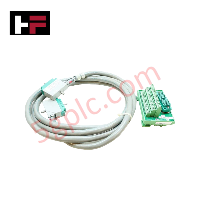
- Mounting: Secure the board to the rack or panel using appropriate hardware. Ensure sufficient clearance is maintained for the high-density ribbon cable routing.
- Signal Wiring: Use shielded twisted-pair cables for all analog and current-sensing inputs. Ensure cable shields are terminated at the cabinet entry to prevent electromagnetic interference (EMI).
- High-Voltage Handling: Observe all safety protocols when connecting high-voltage AC inputs. Verify that all terminal block screws are tightened to the specified torque to prevent arcing or thermal buildup at the connection points.
- Current Sensing: For CT inputs (±5 A) and low current signals (±0.224 A), ensure polarity is strictly maintained according to the system wiring diagram to prevent phase errors in the LCI control loop.
- Grounding: Ensure the board chassis is connected to the protective earth (PE) busbar to provide a stable reference for the differential buffering stages.
Additional Information
- 100% Genuine Parts: All products are original and authentic, ensuring reliable industrial performance.
- 30-Day Refund Guarantee: Return any in-stock item within 30 days in original, unopened packaging for a full refund (excluding shipping and fees).
- 12-Month Warranty: Covers defects in materials or workmanship; excludes misuse, normal wear, or unauthorized modifications.
- Worldwide Shipping: We ship via USPS, UPS, FedEx, and DHL. Delivery times vary by country and may be subject to customs or import fees.
- Support & Contact: Technical and warranty assistance is available anytime. Contact us here: Contact.
- Purchase Guidance: Check product specifications and compatibility carefully before ordering to ensure proper application.

Tech & Buying Guide

Essential SCADA Features for Modern IoT-Enabled Industrial Automation
The convergence of traditional SCADA systems with the Industrial Internet of Things (IIoT) has redefined factory automation. Choosing a robust platform requires more than just standard monitoring capabilities. In this era of Industry 4.0, your supervisory system must bridge the gap between legacy control systems and enterprise-level data integration.

Selecting Rockwell Automation Allen-Bradley PLCs for Small and Mid-Sized Applications
Rockwell Automation remains a cornerstone in global industrial automation. Their Allen-Bradley brand provides a comprehensive portfolio of control systems designed to meet diverse production requirements. Choosing the right programmable logic controller (PLC) is critical for system reliability and scalability. This guide analyzes the Micro and Compact Logix families to help you select the optimal solution for small and medium-scale projects.

Strategic Selection: Choosing the Right SCADA Software for Your PLC Project
In industrial automation, the SCADA (Supervisory Control and Data Acquisition) system acts as the bridge between raw machine data and actionable human intelligence. Selecting the incorrect software platform can lead to integration bottlenecks, scalability issues, and excessive long-term maintenance costs. As an automation consultant with 15 years of experience, I have guided many projects through the selection process. Below are the essential criteria for choosing a platform that ensures both performance and longevity.