


Product Details
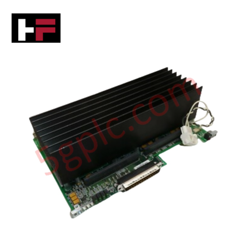
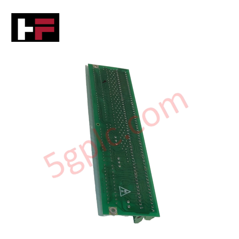
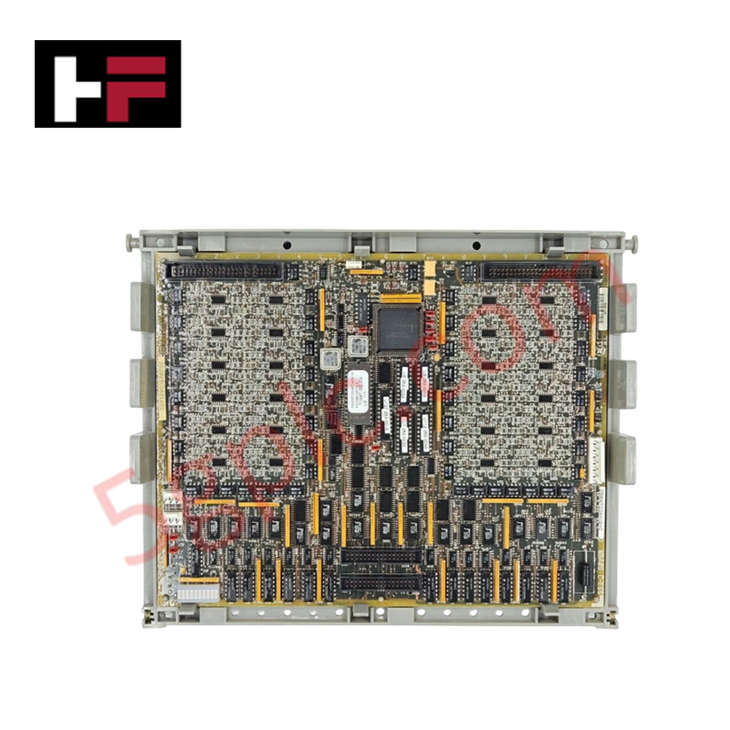
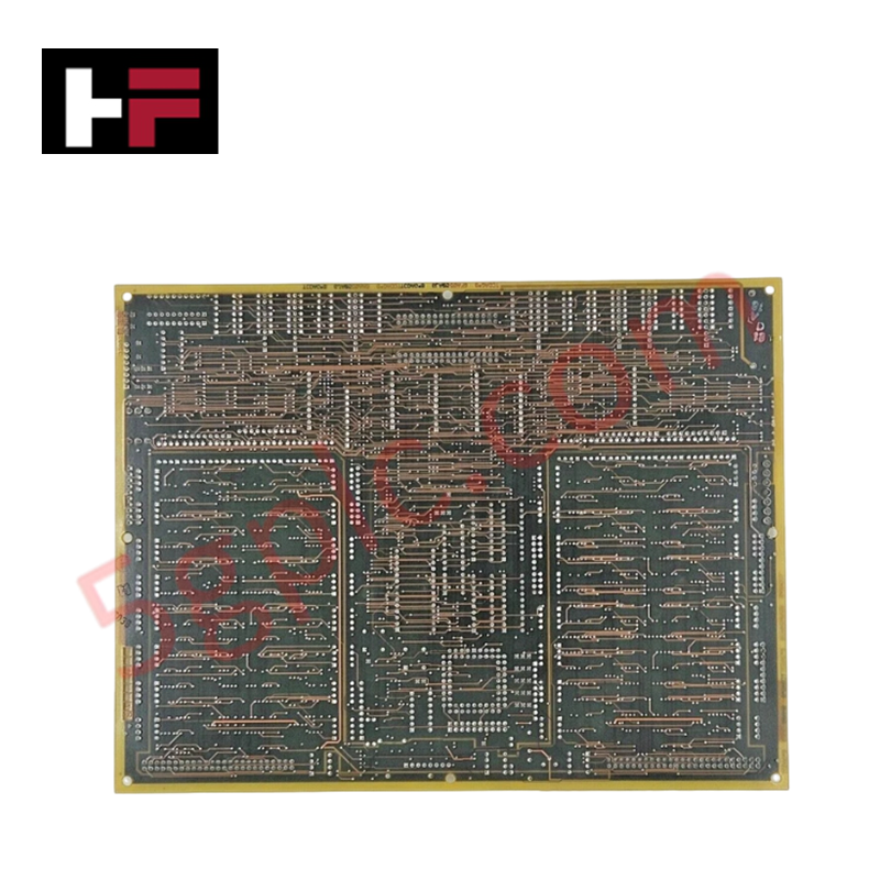
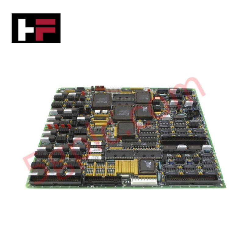
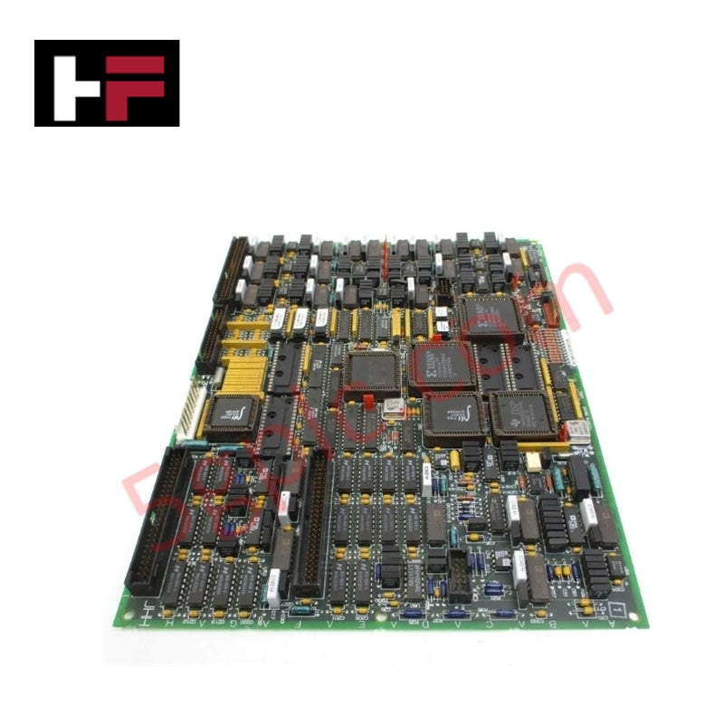
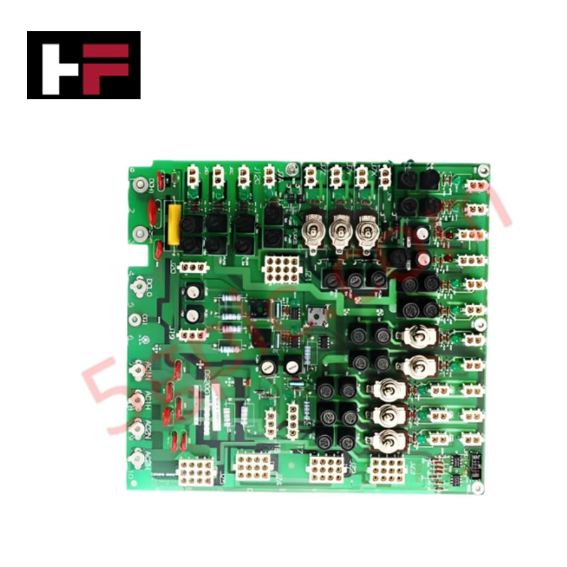
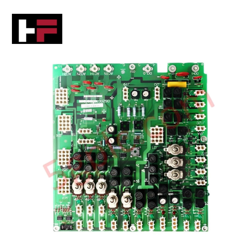
The General Electric IS215VPROH1BD, also cataloged as the IS215VPROH1BD Emergency Turbine Protection Module, operates as a dedicated hardware component for independent overspeed protection and turbine safety monitoring within Mark VI control system platforms.
Hardware Specifications
| Parameter | Specification |
|---|---|
| Model | IS215VPROH1BD |
| Brand | General Electric |
| Origin | United States of America (USA) |
| Frame Rate | Up to 100 Hz |
| MPU Pulse Rate | 2 Hz to 20 kHz |
| Input Supply | 125 V DC (70-145 V DC range) |
| Output Voltage | 5 V DC and 28 V DC |
Industrial Control and Firmware Integration
The IS215VPROH1BD utilizes high-speed internal logic to process Magnetic Pickup (MPU) inputs, providing deterministic overspeed detection. The module supports firmware flash compatibility, ensuring that protection algorithms remain synchronized with the overall Mark VI control architecture. Its internal logic executes independent of the primary turbine controller, facilitating I/O density scaling through seamless integration with TPRO and TREG terminal boards. The module’s backplane bus communication velocity enables real-time transmission of turbine speed status to the primary system database, ensuring high-fidelity monitoring for safety-instrumented functions.
Frequently Asked Questions (FAQ)
Q: Is this module capable of redundant operation?
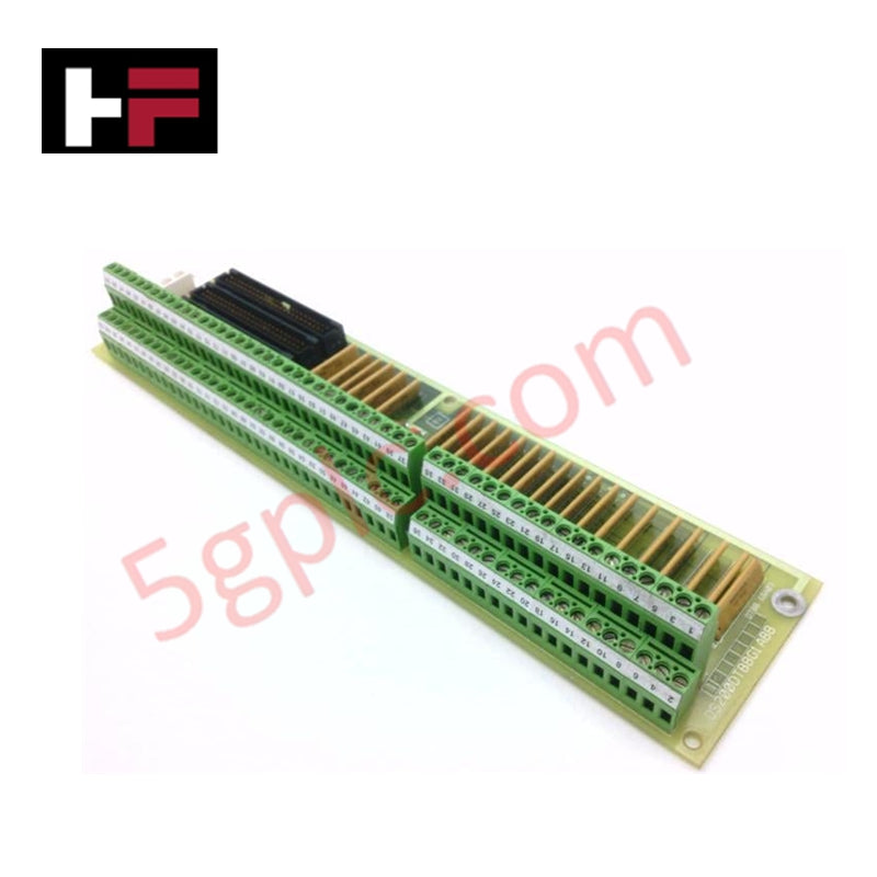
A: Yes, the VPRO board is designed to function as part of an independent and redundant emergency overspeed protection system when paired with TPRO and TREG terminal boards.
Q: What is the input signal range for the speed sensing MPU?
A: The board supports MPU pulse rate inputs ranging from 2 Hz to 20 kHz, allowing for accurate frequency monitoring across a wide spectrum of turbine operational speeds.
Field Installation Guidelines
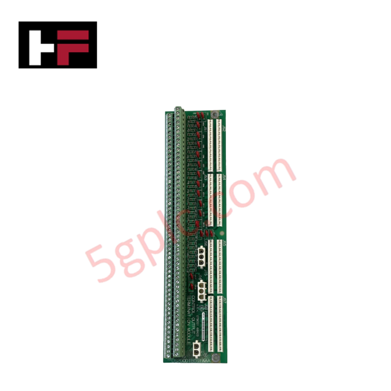
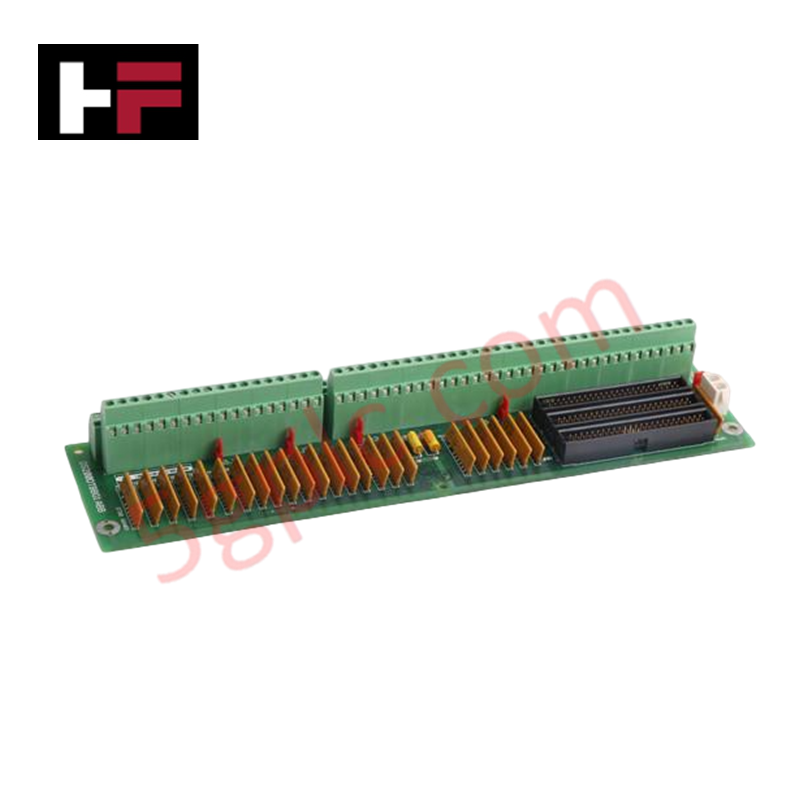
- Terminal Board Interfacing: The VPRO module must be installed in conjunction with TPRO and TREG terminal boards. Ensure all ribbon cable or backplane connections between these boards are firmly seated to maintain the redundancy of the protection path.
- Input Wiring: Use high-quality shielded cabling for MPU signal inputs. Ensure the shield is terminated at the designated ground reference on the terminal board to prevent electromagnetic interference (EMI) from inducing false frequency pulses.
- Power Supply: Connect the 125 V DC input supply (nominal range 70-145 V DC) to the appropriate power terminals. Verify polarity before energizing to prevent damage to internal DC-DC conversion circuits.
- Grounding: Secure the module chassis to the cabinet ground. A low-impedance ground connection is required for the internal safety logic to maintain effective transient suppression and electromagnetic compatibility.
Additional Information
- 100% Genuine Parts: All products are original and authentic, ensuring reliable industrial performance.
- 30-Day Refund Guarantee: Return any in-stock item within 30 days in original, unopened packaging for a full refund (excluding shipping and fees).
- 12-Month Warranty: Covers defects in materials or workmanship; excludes misuse, normal wear, or unauthorized modifications.
- Worldwide Shipping: We ship via USPS, UPS, FedEx, and DHL. Delivery times vary by country and may be subject to customs or import fees.
- Support & Contact: Technical and warranty assistance is available anytime. Contact us here: Contact.
- Purchase Guidance: Check product specifications and compatibility carefully before ordering to ensure proper application.
Tech & Buying Guide

Selecting the Right Cables for Industrial Automation: A Comprehensive Guide
Selecting the appropriate cabling infrastructure is critical for the success of any industrial automation project. Improper cable selection often leads to signal degradation, system instability, and costly downtime. As an automation engineer, I frequently see projects compromised by poor cabling choices in harsh industrial environments. This guide simplifies the complex landscape of cabling to help you make informed decisions for your PLC, DCS, and control systems.

Preventing Spurious Trips in Emergency Stop Systems: A Technical Guide
In industrial automation, the Emergency Stop (E-Stop) pushbutton is the ultimate safety line. However, relying on a single Normally-Closed (NC) contact can sometimes lead to unexpected spurious trips. As a control systems engineer, I have seen these nuisance trips halt entire production lines, causing significant downtime. Understanding why these components fail and how to implement robust architecture is essential for any reliable DCS or PLC-based safety system.

Sequencing Induction Motor Control with PLC Logic: Best Practices
In modern industrial automation, controlling a group of induction motors requires precision and safety. Uncontrolled simultaneous startup of multiple large motors often causes significant voltage dips, potentially triggering protective trips. Therefore, implementing a sequential startup and shutdown strategy is essential. This approach minimizes inrush current and ensures the system operates within established power constraints. A robust PLC program serves as the ideal engine for orchestrating these sequences.