


Product Details
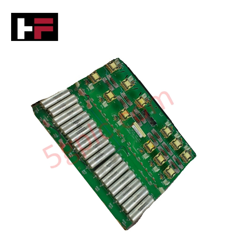
Configured for signal routing within Mark V drive systems, the GE DS200PCCAG7ACB (DS200PCCA Power Connect Card) provides direct physical execution of control interfacing between command circuitry and SCR power bridge assemblies.
Hardware Specifications
| Parameter | Specification |
|---|---|
| Model | DS200PCCAG7ACB |
| Brand | GE |
| Core Performance | SCR power bridge interface, feedback signal relay |
Industrial Control & Firmware Compatibility
The DS200PCCAG7ACB acts as the primary signal conduit between drive control logic and high-power silicon controlled rectifier (SCR) arrays. The board facilitates backplane bus communication velocity by ensuring deterministic transmission of gate-drive commands and feedback loops, including current, voltage, and temperature data. Firmware flash compatibility is managed via the host control processor; the card itself requires specific revision parity to ensure that I/O density scaling aligns with the drive's power bridge configuration. Users must verify hardware revision compatibility before integration to avoid signal latency or gate-triggering errors in the SCR bridge.
Frequently Asked Questions
Q: Does this card support hot-swap functionality?
A: No. The DS200PCCAG7ACB must be installed or removed only when the drive is de-energized and locked out. Hot-swapping poses a risk of voltage transients that can damage the sensitive control circuitry or the SCR gate-drive triggers.
Q: How does this card handle feedback signal integrity?
A: Feedback signals, such as current measurements and temperature readings, are relayed through shielded pathways on the PCB to minimize interference. Ensure that external cabling is correctly shielded to maintain this signal-to-noise ratio during operation.
Field Installation Guidelines
- Connector Alignment: Carefully align the card with the drive backplane slots. Do not force the connection; ensure the card is perpendicular to the backplane to prevent pin damage on the interface headers.
- Shielding Continuity: Ensure that all feedback signal cables are properly grounded at the designated shield termination points on the drive chassis to prevent electromagnetic noise from distorting temperature and voltage feedback data.
- Revision Verification: Confirm that the A-C-B revision code on the board label matches the system design requirements. Mixing incompatible hardware revisions in a drive assembly can lead to gate-triggering misalignment.
- Component Inspection: Prior to installation, inspect the SCR interface connectors for signs of thermal stress or oxidation. Ensure that ribbon cables connecting to the card are fully seated and free from mechanical tension.
Additional Information
- 100% Genuine Parts: All products are original and authentic, ensuring reliable industrial performance.
- 30-Day Refund Guarantee: Return any in-stock item within 30 days in original, unopened packaging for a full refund (excluding shipping and fees).
- 12-Month Warranty: Covers defects in materials or workmanship; excludes misuse, normal wear, or unauthorized modifications.
- Worldwide Shipping: We ship via USPS, UPS, FedEx, and DHL. Delivery times vary by country and may be subject to customs or import fees.
- Support & Contact: Technical and warranty assistance is available anytime. Contact us here: Contact.
- Purchase Guidance: Check product specifications and compatibility carefully before ordering to ensure proper application.


Tech & Buying Guide

Redundant Automation Systems: Ensuring Continuous Uptime in Critical Control Infrastructure
System reliability directly determines operational profitability across high stakes process industries. Modern industrial automation platforms must eliminate single points of failure to prevent catastrophic shutdowns. Deploying fault tolerant architecture safeguards complex facilities against unexpected hardware glitches, network disruptions, and maintenance outages.

Understanding Types of Noise in Electronic Circuits and Control Systems
Signal integrity directly determines measurement accuracy and loop stability across industrial automation environments. Electronic noise introduces unwanted stochastic interference into analog loops, sensor feedback lines, and digital fieldbus networks. Understanding how intrinsic electronic noise and external electromagnetic interference manifest allows control engineers to optimize signal conditioning and shield sensitive instrumentation effectively.

Why 24V DC Power Supplies Standardize Modern Industrial Automation
Industrial control cabinets worldwide rely on 24V DC as the universal power standard for field instrumentation, sensors, and controllers. Walk into any manufacturing plant, and you will find PLCs, human-machine interfaces (HMIs), and smart actuators running on extra-low voltage DC. Standardizing on 24V DC enhances operational safety, lowers cabinet footprint, and maintains steady control performance across factory networks.