


Product Details
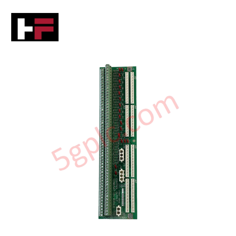
The GE DS200DTBCG1A, also cataloged as the DS200DTBCG1A Contact Output Termination Module, operates as a dedicated hardware component for relay signal termination and solenoid control within the Mark V control system.
Hardware Specifications
| Parameter | Specification |
|---|---|
| Model | DS200DTBCG1A |
| Brand | General Electric |
| Origin | United States (USA) |
| Series | Mark V |
| Product Type | Contact Output Termination Module |
| Weight | Subject to final enclosure configuration |
| Dimensions | Standard Mark V PCB footprint |
| Operating Temp | Industrial standard 0 to 60 deg C |
| Power Consumption | Dependent on connected solenoid load |
Industrial Control & Firmware Compatibility
The DS200DTBCG1A functions as the terminal interface for the TCRA relay board. The module supports backplane bus communication and I/O density scaling by facilitating connections across the Q11, Q21, and Q51 cores. Hardware jumpers on the module enable the configuration of 18 out of the 30 available outputs in the Q51 core for solenoid actuation. In the Q11 core configuration, jumper settings are specifically mapped to support gas manifold blow-off valve control sequences, ensuring deterministic response times for critical output operations.
Frequently Asked Questions
Q: Are the contact outputs on the DS200DTBCG1A hot-swappable?
A: No. The Mark V architecture does not support hot-swapping for the DTBC termination module. The system must be de-energized prior to removing or installing the board to prevent electrical arc damage to the backplane connectors.
Q: How is 125 V DC power supplied to the contact outputs?
A: Power is routed via the J15/J16 connectors linked to the TCPD board in the PD core. Specific configuration in the Q51 core allows for 125 V DC distribution to outputs 16, 17, and 18.
Field Installation Guidelines
- Connector Integrity: Verify that JS1-JS8 connectors are securely seated to ensure reliable signal acquisition from the TCRA board.
- Jumper Configuration: Ensure P1/M1 through P18/M18 jumpers are correctly aligned. In solenoid-enabled configurations, both P and M jumpers must be installed or removed simultaneously to prevent open-circuit faults.
- Grounding: Maintain clean contact surfaces at mounting points to ensure chassis ground continuity.
- Cable Routing: Separate signal-level wiring (JS1-JS8) from solenoid power supply wiring (J8) to mitigate electromagnetic interference (EMI) on the relay control paths.
Additional Information
- 100% Genuine Parts: All products are original and authentic, ensuring reliable industrial performance.
- 30-Day Refund Guarantee: Return any in-stock item within 30 days in original, unopened packaging for a full refund (excluding shipping and fees).
- 12-Month Warranty: Covers defects in materials or workmanship; excludes misuse, normal wear, or unauthorized modifications.
- Worldwide Shipping: We ship via USPS, UPS, FedEx, and DHL. Delivery times vary by country and may be subject to customs or import fees.
- Support & Contact: Technical and warranty assistance is available anytime. Contact us here: Contact.
- Purchase Guidance: Check product specifications and compatibility carefully before ordering to ensure proper application.


Tech & Buying Guide

Redundant Automation Systems: Ensuring Continuous Uptime in Critical Control Infrastructure
System reliability directly determines operational profitability across high stakes process industries. Modern industrial automation platforms must eliminate single points of failure to prevent catastrophic shutdowns. Deploying fault tolerant architecture safeguards complex facilities against unexpected hardware glitches, network disruptions, and maintenance outages.

Understanding Types of Noise in Electronic Circuits and Control Systems
Signal integrity directly determines measurement accuracy and loop stability across industrial automation environments. Electronic noise introduces unwanted stochastic interference into analog loops, sensor feedback lines, and digital fieldbus networks. Understanding how intrinsic electronic noise and external electromagnetic interference manifest allows control engineers to optimize signal conditioning and shield sensitive instrumentation effectively.

Why 24V DC Power Supplies Standardize Modern Industrial Automation
Industrial control cabinets worldwide rely on 24V DC as the universal power standard for field instrumentation, sensors, and controllers. Walk into any manufacturing plant, and you will find PLCs, human-machine interfaces (HMIs), and smart actuators running on extra-low voltage DC. Standardizing on 24V DC enhances operational safety, lowers cabinet footprint, and maintains steady control performance across factory networks.